- 您現(xiàn)在的位置:買賣IC網(wǎng) > PDF目錄45010 > M30201M6-XXXFP 16-BIT, MROM, 10 MHz, MICROCONTROLLER, PQFP56 PDF資料下載
參數(shù)資料
| 型號: | M30201M6-XXXFP |
| 元件分類: | 微控制器/微處理器 |
| 英文描述: | 16-BIT, MROM, 10 MHz, MICROCONTROLLER, PQFP56 |
| 封裝: | PLASTIC, QFP-56 |
| 文件頁數(shù): | 10/28頁 |
| 文件大小: | 2425K |
| 代理商: | M30201M6-XXXFP |
第1頁第2頁第3頁第4頁第5頁第6頁第7頁第8頁第9頁當(dāng)前第10頁第11頁第12頁第13頁第14頁第15頁第16頁第17頁第18頁第19頁第20頁第21頁第22頁第23頁第24頁第25頁第26頁第27頁第28頁
Clock Generating Circuit
Mitsubishi microcomputers
M30201 Group
SINGLE-CHIP 16-BIT CMOS MICROCOMPUTER
17
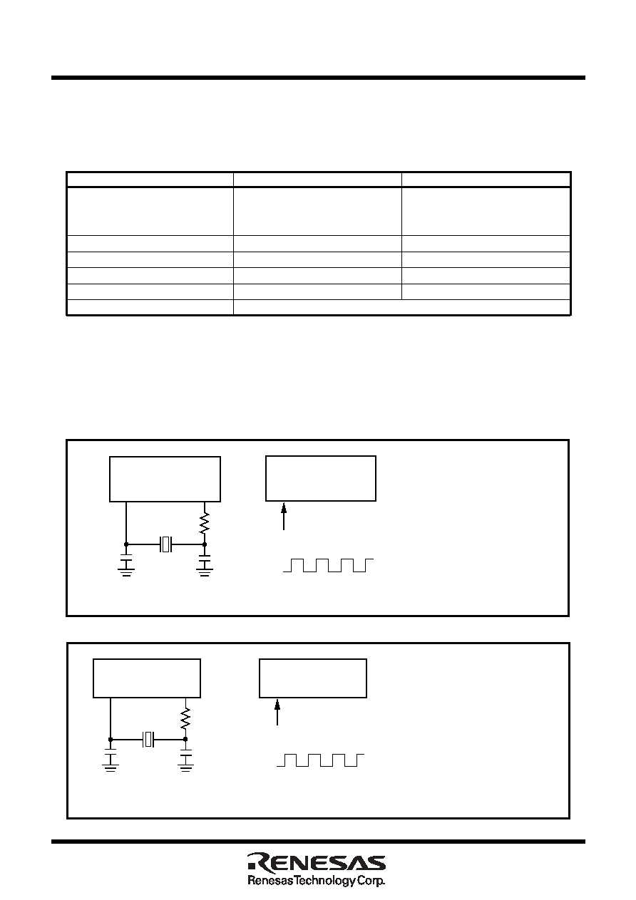
Figure 1.16. Examples of sub-clock
Table 1.2. Main clock and sub-clock generating circuits
Clock Generating Circuit
The clock generating circuit contains two oscillator circuits that supply the operating clock sources to the
CPU and internal peripheral units.
Example of oscillator circuit
Figure 1.15 shows some examples of the main clock circuit, one using an oscillator connected to the circuit,
and the other one using an externally derived clock for input. Figure 1.16 shows some examples of sub-
clock circuits, one using an oscillator connected to the circuit, and the other one using an externally derived
clock for input. Circuit constants in Figures 15 and 16 vary with each oscillator used. Use the values
recommended by the manufacturer of your oscillator.
Figure 1.15. Examples of main clock
Main clock generating circuit
Sub clock generating circuit
Use of clock
CPU’s operating clock source
Internal peripheral units’
Timer A/B/X’s count clock
operating clock source
source
Usable oscillator
Ceramic or crystal oscillator
Crystal oscillator
Pins to connect oscillator
XIN, XOUT
XCIN, XCOUT
Oscillation stop/restart function
Available
Oscillator status immediately after reset
Oscillating
Stopped
Other
Externally derived clock can be input
M30201
(Built-in feedback resistor)
XIN
XOUT
Externally derived clock
Open
Vcc
Vss
M30201
(Built-in feedback resistor)
XIN
XOUT
Rd
CIN
COUT
(Note)
Note: Insert a damping resistor if
required. The resistance will
vary depending on the
oscillator and the oscillation
drive capacity setting. Use the
value recommended by the
maker of the oscillator.
When the oscillation drive
capacity is set to low, check
that oscillation is stable. Also,
if the oscillator manufacturer's
data sheet specifies that a
feedback resistor be added
external to the chip, insert a
feedback resistor between XIN
and XOUT following the
instruction.
M30201
(Built-in feedback resistor)
XCIN
XCOUT
Externally derived clock
Open
Vcc
Vss
M30201
(Built-in feedback resistor)
XCIN
XCOUT
(Note)
CCIN
CCOUT
RCd
Note: Insert a damping resistor if
required. The resistance will
vary depending on the oscillator
and the oscillation drive
capacity setting. Use the value
recommended by the maker of
the oscillator.
When the oscillation drive
capacity is set to low, check that
oscillation is stable. Also,
if the oscillator manufacturer's
data sheet specifies that a
feedback resistor be added
external to the chip, insert a
feedback resistor between
XCIN and XCOUT following the
instruction.
相關(guān)PDF資料 |
PDF描述 |
|---|---|
| M30218MC-AXXXFP | 16-BIT, MROM, 10 MHz, MICROCONTROLLER, PQFP100 |
| M30218FCFP | 16-BIT, FLASH, 10 MHz, MICROCONTROLLER, PQFP100 |
| M30221FCFP | 16-BIT, FLASH, 10 MHz, MICROCONTROLLER, PQFP120 |
| M30221M4-XXXFP | 16-BIT, MROM, 10 MHz, MICROCONTROLLER, PQFP120 |
| M30221M8-XXXFP | 16-BIT, MROM, 10 MHz, MICROCONTROLLER, PQFP120 |
相關(guān)代理商/技術(shù)參數(shù) |
參數(shù)描述 |
|---|---|
| M30201M6-XXXSP | 制造商:RENESAS 制造商全稱:Renesas Technology Corp 功能描述:16-BIT SINGLE-CHIP MICROCOMPUTER M16C FAMILY |
| M30201MST-XXXFP | 制造商:RENESAS 制造商全稱:Renesas Technology Corp 功能描述:SINGLE-CHIP 16-BIT CMOS MICROCOMPUTER |
| M30201MST-XXXSP | 制造商:RENESAS 制造商全稱:Renesas Technology Corp 功能描述:SINGLE-CHIP 16-BIT CMOS MICROCOMPUTER |
| M30201MS-XXXFP | 制造商:RENESAS 制造商全稱:Renesas Technology Corp 功能描述:SINGLE-CHIP 16-BIT CMOS MICROCOMPUTER |
| M30201MS-XXXSP | 制造商:RENESAS 制造商全稱:Renesas Technology Corp 功能描述:SINGLE-CHIP 16-BIT CMOS MICROCOMPUTER |
發(fā)布緊急采購,3分鐘左右您將得到回復(fù)。