- 您現(xiàn)在的位置:買賣IC網(wǎng) > PDF目錄45010 > M30100M3T-XXXFP 16-BIT, MROM, 16 MHz, MICROCONTROLLER, PQFP32 PDF資料下載
參數(shù)資料
| 型號: | M30100M3T-XXXFP |
| 元件分類: | 微控制器/微處理器 |
| 英文描述: | 16-BIT, MROM, 16 MHz, MICROCONTROLLER, PQFP32 |
| 封裝: | 7 X 7 MM, 0.80 MM PITCH, PLASTIC, LQFP-32 |
| 文件頁數(shù): | 140/164頁 |
| 文件大小: | 3302K |
| 代理商: | M30100M3T-XXXFP |
第1頁第2頁第3頁第4頁第5頁第6頁第7頁第8頁第9頁第10頁第11頁第12頁第13頁第14頁第15頁第16頁第17頁第18頁第19頁第20頁第21頁第22頁第23頁第24頁第25頁第26頁第27頁第28頁第29頁第30頁第31頁第32頁第33頁第34頁第35頁第36頁第37頁第38頁第39頁第40頁第41頁第42頁第43頁第44頁第45頁第46頁第47頁第48頁第49頁第50頁第51頁第52頁第53頁第54頁第55頁第56頁第57頁第58頁第59頁第60頁第61頁第62頁第63頁第64頁第65頁第66頁第67頁第68頁第69頁第70頁第71頁第72頁第73頁第74頁第75頁第76頁第77頁第78頁第79頁第80頁第81頁第82頁第83頁第84頁第85頁第86頁第87頁第88頁第89頁第90頁第91頁第92頁第93頁第94頁第95頁第96頁第97頁第98頁第99頁第100頁第101頁第102頁第103頁第104頁第105頁第106頁第107頁第108頁第109頁第110頁第111頁第112頁第113頁第114頁第115頁第116頁第117頁第118頁第119頁第120頁第121頁第122頁第123頁第124頁第125頁第126頁第127頁第128頁第129頁第130頁第131頁第132頁第133頁第134頁第135頁第136頁第137頁第138頁第139頁當(dāng)前第140頁第141頁第142頁第143頁第144頁第145頁第146頁第147頁第148頁第149頁第150頁第151頁第152頁第153頁第154頁第155頁第156頁第157頁第158頁第159頁第160頁第161頁第162頁第163頁第164頁
Under
development
Tentative Specifications REV.E1
Specifications in this manual are tentative and subject to change.
Mitsubishi microcomputers
M30100/M30102 Group
SINGLE-CHIP 16-BIT CMOS MICROCOMPUTER
Timer Y
76
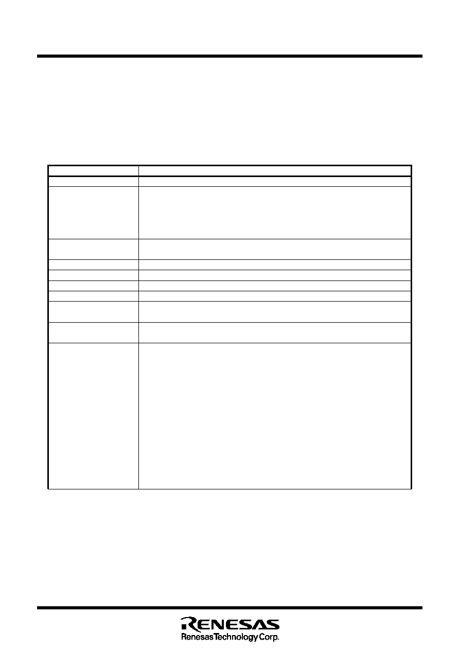
(2) Programmable waveform generation mode
In this mode, the microcontroller, while counting the set values of Timer Y primary and Timer Y sec-
ondary alternately, outputs from the TYOUT pin a waveform whose polarity is inverted each time Timer
Y primary or Timer Y secondary underflows. (See Table 1.14.9) A counting starts by counting the set
value in the Timer Y primary. Figure 1.14.18 shows Timer Y, Z mode register in programmable wave-
form generation mode. Figure 1.14.19 shows the operation example.
Item
Specification
Count source
f1, f8, ring oscillator output, fC32
Count operation
Down count
When the timer underflows, it reloads the contents of primary reload register and sec-
ondary reload register alternately before continuing counting.
When a counting stops, the timer reloads the content of the reload register before it
stops.
Divide ratio
fi/(n+1)/((m+1)+(l+1))
n : Set value of Prescaler Y, m: Set value of Timer Y primary, l: Set value of Timer Y secondary
Count start condition
Count start flag is set (=1)
Count stop condition
Count start flag is reset (=0) (Note 1)
Interrupt request generation timing When Timer Y underflows during secondary period
TYOUT pin function
Pulse output (Note 2)
Read from timer
Count value can be read out by reading Timer Y primary register.
Same applies to Prescaler Y register. (Note 3)
Write to timer
When a value is written to Timer Y primary register, it is written to only reload register.
Same applies to Timer Y secondary register and Prescaler Y register. (Note 4)
Select function
Output level latch select function
The output level of a waveform being counted during primary and secondary periods is
selectable.
Programmable waveform generation output switching function
Can select either programmable waveform or the value of Port P32 register for output.
(Note 5)
Waveform extend function (Note 6)
The waveform output primary period and secondary period can each be extended 0.5
cycles of the count source
Frequency when waveform extended: 2xfi/((2x(m+1))+(2x(l+1))+TYPUM0+TYPUM1)
Duty: (2x(m+1)+TYPUM0)/((2x(m+1)+TYPUM0)+(2x(l+1)+TYPUM1))
m: set value of Timer Y primary, l: set value of Timer Y secondary
TYPUM0: Timer Y primary waveform extension control bit
TYPUM1: Timer Y secondary waveform extension control bit
Note 1: When the count is stopped, the Timer Y interrupt request flag becomes "1" and an interrupt may occur. Thus,
interrupts must be disabled before the count is stopped. Furthermore, set the Timer Y interrupt request flag to "0"
before starting counting again.
Note 2: When the counting stopped, the pin is the secondary period output level.
Note 3: Even when counting the secondary period, read out the Timer Y primary register.
Note 4: The set value of Timer Y secondary register and waveform extension control bits as well as Timer Y primary
register are made effective by writing a value to the Timer Y primary register. The written values are reflected to
the waveform output from the next primary period after writing to the Timer Y primary register.
Note 5: The output is switched in sync with timer Y secondary underflow.
Note 6: When using the waveform extend function, the Prescaler Y register must be set to "0016".
Table 1.14.9. Specifications of programmable waveform generation mode
相關(guān)PDF資料 |
PDF描述 |
|---|---|
| M30100M3-XXXFP | 16-BIT, MROM, 16 MHz, MICROCONTROLLER, PQFP32 |
| M30100F3FP | 16-BIT, FLASH, 16 MHz, MICROCONTROLLER, PQFP32 |
| M30102M3T-XXXFP | 16-BIT, MROM, 16 MHz, MICROCONTROLLER, PQFP48 |
| M30102M3-XXXFP | 16-BIT, MROM, 16 MHz, MICROCONTROLLER, PQFP48 |
| M30100M3-XXXFP | 16-BIT, MROM, 16 MHz, MICROCONTROLLER, PQFP32 |
相關(guān)代理商/技術(shù)參數(shù) |
參數(shù)描述 |
|---|---|
| M30100T3-RPD-E | 制造商:Renesas Electronics Corporation 功能描述:DEV EMULATOR POD M16C/10 SERIES - Bulk |
| M30100T-PTC | 制造商:RENESAS 制造商全稱:Renesas Technology Corp 功能描述:Converter for Connecting 32-pin 0.8mm-pitch QFP for M30100T-PRB (for M16C/10 Group M30100) |
| M30-1010046 | 功能描述:集管和線殼 1.25MM FEMALE CRIMP TIN PK OF 105 RoHS:否 產(chǎn)品種類:1.0MM Rectangular Connectors 產(chǎn)品類型:Headers - Pin Strip 系列:DF50 觸點(diǎn)類型:Pin (Male) 節(jié)距:1 mm 位置/觸點(diǎn)數(shù)量:16 排數(shù):1 安裝風(fēng)格:SMD/SMT 安裝角:Right 端接類型:Solder 外殼材料:Liquid Crystal Polymer (LCP) 觸點(diǎn)材料:Brass 觸點(diǎn)電鍍:Gold 制造商:Hirose Connector |
| M3010102636207.32LLZZ | 制造商:3M Electronic Products Division 功能描述:QUOTE # V05-0068 |
| M30102 | 制造商:RENESAS 制造商全稱:Renesas Technology Corp 功能描述:SINGLE-CHIP 16-BIT CMOS MICROCOMPUTER |
發(fā)布緊急采購,3分鐘左右您將得到回復(fù)。