- 您現(xiàn)在的位置:買賣IC網(wǎng) > PDF目錄358968 > LZ95B25 (Sharp Corporation) Subcarrier Generator LSl for CCD PDF資料下載
參數(shù)資料
| 型號: | LZ95B25 |
| 廠商: | Sharp Corporation |
| 英文描述: | Subcarrier Generator LSl for CCD |
| 中文描述: | 副載波發(fā)生器勞基防治荒漠化公約 |
| 文件頁數(shù): | 3/5頁 |
| 文件大小: | 97K |
| 代理商: | LZ95B25 |
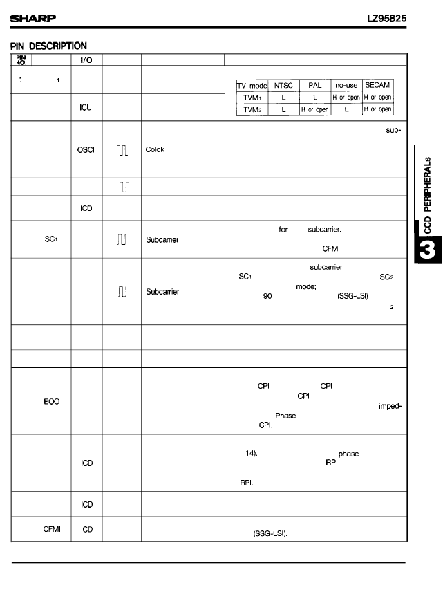
S Y MBOL
_..
I POLARITY I
PIN NAME
FUNCTION
TVM
Icu
T V
mode 1
These input pins to select TV standards.
—
2
TVM2
—
T V
mode 2
An input pin for the signal 4 times the color
carrier frequency.
At NTSC mode
At PAL mode
At SECAM mode : 17.625 MHz
3
4FSI
input
: 14.31818 MHz
: 17.734475 MHz
4
4FS0
Osco
Clock output
The output is the inverse 4FSI (pin 4).
5
TSTI
Test pin 1
A test pin, Set open or to L level in the Normal
mode,
—
An output pin
the signals is 1/4 the 4FSI (pin 3). The signal is
reset by color frame pulse
color
The frequency of
6
02M
output 1
(pin 13).
An output pin for color
of
(pin 4) is 180 degree, the phase of
80 degree in NTSC
of SC2 is
degree when LSW
and 270 degree when LSW is H level. The SC is
same as the phase of SC I in SECAM mode.
When the phase
is
7
SC2
02M
output 2
in PAL mode, the phase
is L level
8
TST2
ICD
Test pin 2
A test pin. Set open or to L level in the Normal
mode.
—
9
GND
—
—
Ground
A grounding pin.
Phase comparator output for input signals RPI (pin
14) and
(pin 16). When
is Low level. When
is delayed, output is High
level. When phases are equal, the terminal
ance is High.
comparator comparates rising
edge of
is advanced, output
Phase comparator
output
10
TO
—
The CPCH input pin switches the polarity of RPI
(pin
When CPCH is L level,
comparates rising edge of
level, phase comparator comparates falling edge
of
comparator
When CPCH is H
11
CPCH
—
Polarity select input
12
T S T 3
–
Test pin 3
A test pin. Set open or to L level in the Normal
mode.
13
–
Color frame input
An input pin for color frame signal; Connect to
CFMO
301
相關(guān)PDF資料 |
PDF描述 |
|---|---|
| LZ9FD34 | Single-chip Driver IC for 270 k/320 k/ 410 k/470 k-pixel B/W CCDs |
| LZ9GF16 | XO 40MHZ 50PPM 3.3V SMD-7050 TR-7-PL |
| LZ9GG32M | XO 50MHZ 50PPM 3.3V SMD-7050 TR-7-PL |
| LZ9GG33 | XO 66MHZ 50PPM 3.3V SMD-7050 TR-7-PL |
| LZ9GG33M | OSCILLATOR 66.6667MHZ SMD |
相關(guān)代理商/技術(shù)參數(shù) |
參數(shù)描述 |
|---|---|
| LZ95D37 | 制造商:未知廠家 制造商全稱:未知廠家 功能描述:TV/Video Sync Circuit |
| LZ95D37/M | 制造商:未知廠家 制造商全稱:未知廠家 功能描述:TV/Video Sync Circuit |
| LZ95D37M | 制造商:未知廠家 制造商全稱:未知廠家 功能描述:TV/Video Sync Circuit |
| LZ95D42 | 制造商:未知廠家 制造商全稱:未知廠家 功能描述:TV/Video Sync Circuit |
| LZ95D42/M | 制造商:未知廠家 制造商全稱:未知廠家 功能描述:TV/Video Sync Circuit |
發(fā)布緊急采購,3分鐘左右您將得到回復(fù)。