- 您現(xiàn)在的位置:買賣IC網(wǎng) > PDF目錄45007 > LX1571IDM-TR (MICROSEMI CORP-ANALOG MIXED SIGNAL GROUP) 1 A SWITCHING CONTROLLER, PDSO8 PDF資料下載
參數(shù)資料
| 型號: | LX1571IDM-TR |
| 廠商: | MICROSEMI CORP-ANALOG MIXED SIGNAL GROUP |
| 元件分類: | 穩(wěn)壓器 |
| 英文描述: | 1 A SWITCHING CONTROLLER, PDSO8 |
| 封裝: | LEAD FREE, PLASTIC, SOIC-8 |
| 文件頁數(shù): | 11/12頁 |
| 文件大小: | 293K |
| 代理商: | LX1571IDM-TR |
PHASE MODULATED AC SYNCHRONOUS SECONDARY-SIDE CONTROLLER
LX1570/1571
PRODUCT DA T ABOOK 1996/1997
Copyright 1997
Rev. 0.9.3a 9/15/2004
8
P RELIMINAR Y D AT A S HEET
START-UP OPERATION
Using the main Block Diagram and the LX157x V
CC Start-Up
Voltage Timing Diagram (Figure 5) as a reference, when the V
CC
voltage passes the UVLO threshold (16V typ.), the output of the
UVLO comparator changes to the "HI" state, which causes the
following: a) provides biasing for internal circuitry, and
b)
enables the output drive and the HICCUP latch. This signal sets
the "Q" output of the HICCUP latch "LO", allowing the soft-start
(S.S.) capacitor voltage to ramp up, forcing the regulator output
to follow this voltage. Since the IC provides a constant current
source for charging the S.S. capacitor, the resulting waveform is
a smooth linear ramp, which provides lower in-rush current
during start up.
The Start-Up Timing Diagram (Figure 6) shows the output
voltage and the S.S. capacitor during start up. Notice that the
output voltage does not respond to the S.S. capacitor until this
voltage goes above
≈0.65 volts, allowing this pin to be used as an
external shutdown pin. The value of the soft start capacitor must
be selected such that its ramp up time (t
RAMP) is always greater than
the start up time of the converter, so that the converter is able to
follow the soft-start capacitor.
It is recommended that the soft start capacitor is always selected
such that its ramp up time (t
RAMP) be at least 4 times greater than
the converter's minimum start-up time. Equations 1 and 2 show
how to select this capacitor.
t
RAMP = 4 *
Equation 1
Once t
RAMP is
known, the soft-start capacitor can then be
calculated as follows:
C
SS =
Equation 2
where C
SS is in F and tRAMP is in ms.
Example:
If C
O = 1600F, VO = 12V, IO = 4A
t
RAMP = 4 *
= 19.2ms
C
SS =
= 0.55F
The LX1570/71 series also features micropower start-up current
that allows these controllers to be powered off the transformer
voltage via a low-power resistor and a start-up capacitor. After the
IC starts operating, the output of the converter can be used to
power the IC. In applications where the output is less than the
minimum operating voltage of the IC, an extra winding on the
inductor can be used to perform the same function. The start-up
capacitor must also be selected so that it can supply the power to
the IC long enough for the output of the converter to ramp up
beyond the start-up threshold of the IC. Equation 3 shows how
to select the start-up capacitor.
C
ST = 2
Equation 3
where: I
Q
≡ Dynamic operating current of the IC
t
ST
≡ Time for the bootstrap voltage to go above
the minimum operating voltage (10V typ.)
V
HYST ≡
Minimum hysteresis voltage of the IC
Example: If I
Q = 30mA, tST = 19ms, VHYST = 5.5V
C
ST = 2
= 207F
IC DESCRIPTION
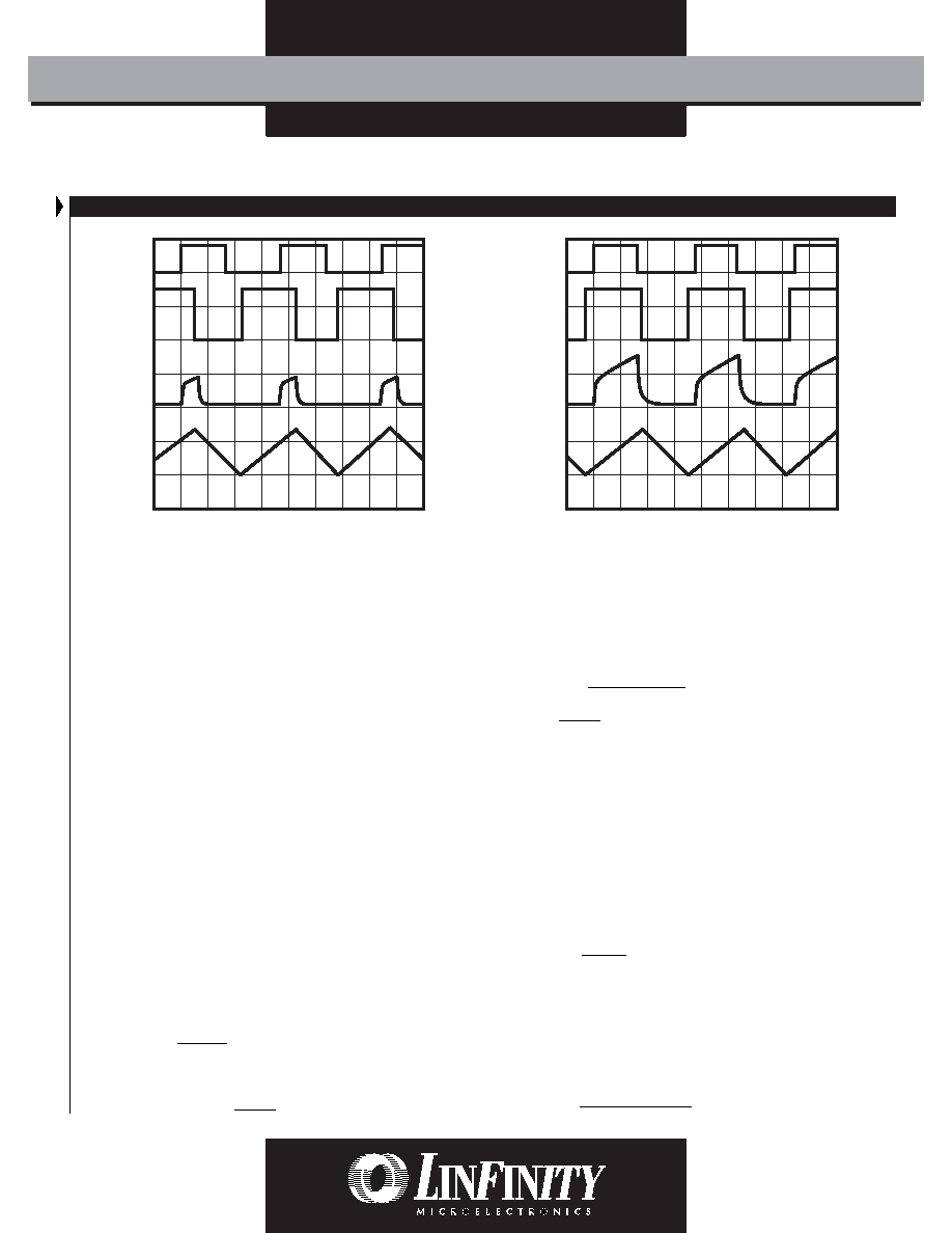
2s / Div.
Transformer
Voltage
LX157x
OUT DRV
LX1571
C.S. Signal
C
T Voltage
2s / Div.
Transformer
Voltage
LX157x
OUT DRV
LX1571
C.S. Signal
C
T Voltage
FIGURE 4A — STEADY-STATE OPERATION TIMING DIAGRAM
(NORMAL MODE)
FIGURE 4B — STEADY-STATE OPERATION TIMING DIAGRAM
(MAXIMUM DUTY CYCLE)
I
Q * tST
V
H
19.2
35
1600 * 10
-6 * 12
4
t
RAMP
35
C
O * VO
I
O
30 * 10
-3 * 19 * 10-3
5.5
相關PDF資料 |
PDF描述 |
|---|---|
| LX1570IDMT | 1 A SWITCHING CONTROLLER, 100 kHz SWITCHING FREQ-MAX, PDSO8 |
| LX1571MY | 1 A SWITCHING CONTROLLER, 100 kHz SWITCHING FREQ-MAX, CDIP8 |
| LX1571CM | 1 A SWITCHING CONTROLLER, 100 kHz SWITCHING FREQ-MAX, PDIP8 |
| LX1571IDM | 1 A SWITCHING CONTROLLER, 100 kHz SWITCHING FREQ-MAX, PDSO8 |
| LX1571IDMT | 1 A SWITCHING CONTROLLER, 100 kHz SWITCHING FREQ-MAX, PDSO8 |
相關代理商/技術參數(shù) |
參數(shù)描述 |
|---|---|
| LX1571IM | 功能描述:IC REG CTRLR ISO PWM CM 8-DIP RoHS:是 類別:集成電路 (IC) >> PMIC - 穩(wěn)壓器 - DC DC 切換控制器 系列:- 標準包裝:4,000 系列:- PWM 型:電壓模式 輸出數(shù):1 頻率 - 最大:1.5MHz 占空比:66.7% 電源電壓:4.75 V ~ 5.25 V 降壓:是 升壓:無 回掃:無 反相:無 倍增器:無 除法器:無 Cuk:無 隔離:無 工作溫度:-40°C ~ 85°C 封裝/外殼:40-VFQFN 裸露焊盤 包裝:帶卷 (TR) |
| LX1571MY | 功能描述:IC REG CTRLR ISO PWM CM 8-DIP RoHS:是 類別:集成電路 (IC) >> PMIC - 穩(wěn)壓器 - DC DC 切換控制器 系列:- 標準包裝:4,000 系列:- PWM 型:電壓模式 輸出數(shù):1 頻率 - 最大:1.5MHz 占空比:66.7% 電源電壓:4.75 V ~ 5.25 V 降壓:是 升壓:無 回掃:無 反相:無 倍增器:無 除法器:無 Cuk:無 隔離:無 工作溫度:-40°C ~ 85°C 封裝/外殼:40-VFQFN 裸露焊盤 包裝:帶卷 (TR) |
| LX15RQ-75884 | 制造商:Banner Engineering 功能描述:LX15RQ-75884 LO Output |
| LX160VB10RM12X20LL | 制造商:未知廠家 制造商全稱:未知廠家 功能描述:LXA/LX Series |
| LX160VB22RM16X25LL | 制造商:未知廠家 制造商全稱:未知廠家 功能描述:LXA/LX Series |
發(fā)布緊急采購,3分鐘左右您將得到回復。