- 您現(xiàn)在的位置:買(mǎi)賣(mài)IC網(wǎng) > PDF目錄45001 > LV8041FN (SANYO SEMICONDUCTOR CO LTD) STEPPER MOTOR CONTROLLER, 0.6 A, QCC52 PDF資料下載
參數(shù)資料
| 型號(hào): | LV8041FN |
| 廠商: | SANYO SEMICONDUCTOR CO LTD |
| 元件分類(lèi): | 運(yùn)動(dòng)控制電子 |
| 英文描述: | STEPPER MOTOR CONTROLLER, 0.6 A, QCC52 |
| 封裝: | 7 X 7 MM, VQFN-52 |
| 文件頁(yè)數(shù): | 12/24頁(yè) |
| 文件大?。?/td> | 802K |
| 代理商: | LV8041FN |
第1頁(yè)第2頁(yè)第3頁(yè)第4頁(yè)第5頁(yè)第6頁(yè)第7頁(yè)第8頁(yè)第9頁(yè)第10頁(yè)第11頁(yè)當(dāng)前第12頁(yè)第13頁(yè)第14頁(yè)第15頁(yè)第16頁(yè)第17頁(yè)第18頁(yè)第19頁(yè)第20頁(yè)第21頁(yè)第22頁(yè)第23頁(yè)第24頁(yè)
LV8041FN
No.7944-2/24
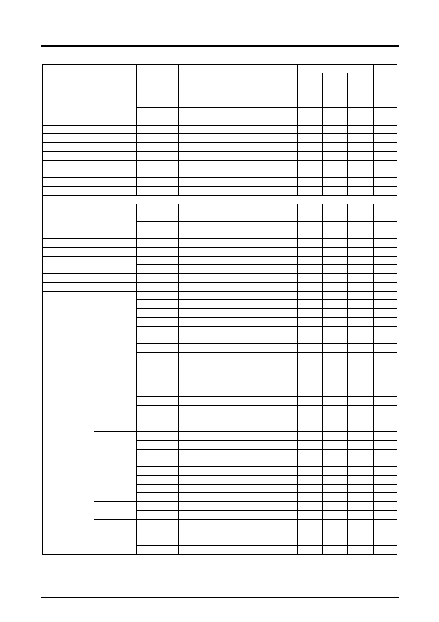
Electrical Characteristics at Ta = 25°C, VM = 5 V, VCC = 5 V
Ratings
Parameter
Symbol
Conditions
min
typ
max
Unit
Standby mode current drain
Istn
ST
= low
1
A
IM
ST
=high
PWM5
= PWM6 = IN72 = high, No load
50
100
A
Current drain
ICC
ST
=high
PWM5
= PWM6 = IN72 =high, No load
3.5
4.5
5.5
mA
VCC low-voltage cutoff voltage
VthVCC
2.1
2.35
2.6
V
Low-voltage sensing hysteresis
VthHIS
100
150
200
mV
VG reference voltage
VGL
4.5
4.7
5.0
V
Charge pump step-up voltage
VGH
8.5
9
9.5
V
Charge pump startup time
tONG
C (VGH)
= 0.1 F
0.1
0.2
ms
Charge pump oscillator frequency
Fchg
R
= 20 k
100
125
150
kHz
Thermal shutdown temperature
TSD
Design guarantee value
150
160
170
°C
Thermal shutdown hysteresis
TSD
Design guarantee value
5
10
20
°C
Stepping Motor Drivers (Channels 1, 2, 3, and 4)
Ronu
Ta
= 25°C, IO = 400mA,
Upper side on-resistance
0.45
0.55
Output on-resistance
Rond
Ta
= 25°C, IO = 400mA,
Lower side on-resistance
0.45
0.55
Output leakage current
IOleak
1
50
A
Diode forward voltage
VD1
ID
= 400mA
0.6
0.9
1.2
V
IINL
VIN = 0 V (ST, CLK12, CLK34)
1.0
A
Logic pin input current
IINH
VIN = 5 V (ST, CLK12, CLK34)
50
70
A
Logic high-level input voltage
VINH
ST, CLK12, CLK34
3.5
V
Logic low-level input voltage
VINL
ST, CLK12, CLK34
1.5
V
Step 16 (Initial state, channel 1 comparator level)
0.188
0.2
0.218
V
Step 15 (Initial state
+1)
0.188
0.2
0.218
V
Step 14 (Initial state
+2)
0.188
0.2
0.218
V
Step 13 (Initial state
+3)
0.177
0.192
0.207
V
Step 12 (Initial state
+4)
0.170
0.185
0.200
V
Step 11 (Initial state
+5)
0.163
0.178
0.193
V
Step 10 (Initial state
+6)
0.156
0.171
0.186
V
Step 9 (Initial state
+7)
0.148
0.163
0.178
V
Step 8 (Initial state
+8)
0.133
0.148
0.163
V
Step 7 (Initial state
+9)
0.117
0.132
0.147
V
Step 6 (Initial state
+10)
0.100
0.115
0.130
V
Step 5 (Initial state
+11)
0.083
0.098
0.113
V
Step 4 (Initial state
+12)
0.065
0.080
0.095
V
Step 3 (Initial state
+13)
0.050
0.062
0.077
V
Step 2 (Initial state
+14)
0.030
0.043
0.058
V
4W1-2 phase
drive
Step 1 (Initial state
+15)
0.010
0.023
0.038
V
Step 16 (Initial state, channel 1 comparator level)
0.188
0.2
0.218
V
Step 14 (Initial
+1)
0.188
0.2
0.218
V
Step 12 (Initial
+2)
0.170
0.185
0.200
V
Step 10 (Initial
+3)
0.156
0.171
0.186
V
Step 8 (Initial
+4)
0.133
0.148
0.163
V
Step 6 (Initial
+5)
0.100
0.115
0.130
V
Step 4 (Initial
+6)
0.065
0.080
0.095
V
2W1-2 phase
drive
Step 2 (Initial
+7)
0.030
0.043
0.058
V
Step 16 (Initial state, channel 1 comparator level)
0.188
0.2
0.218
V
1-2 phase drive
Step 8 (Initial state + 1)
0.133
0.148
0.163
V
Current selection
reference voltage
levels
2-phase drive
Step 8
0.188
0.2
0.218
V
Chopping frequency
Fchop
R
= 20 k
100
125
150
kHz
VMOH
IMO
= 50 A, VM = 5V
4.5
4.9
VCC
V
Monitor pin (MO pin) output voltage
VMOL
IMO
= 50 A
0
0.1
0.5
V
Continued on next page
相關(guān)PDF資料 |
PDF描述 |
|---|---|
| LV8041FN | STEPPER MOTOR CONTROLLER, 0.6 A, QCC52 |
| LV8044LP | DISK DRIVE MOTOR CONTROLLER, QCC40 |
| LV8044LP | DISK DRIVE MOTOR CONTROLLER, QCC40 |
| LV8048CS | STEPPER MOTOR CONTROLLER, 0.8 A, PBGA36 |
| LV8052LP | STEPPER MOTOR CONTROLLER, 0.6 A, QCC24 |
相關(guān)代理商/技術(shù)參數(shù) |
參數(shù)描述 |
|---|---|
| LV8042LG | 制造商:SANYO 制造商全稱(chēng):Sanyo Semicon Device 功能描述:Bi-CMOS IC For Digital Still Cameras 7-Channel Single-Chip Motor Driver ICs |
| LV8044LP | 制造商:SANYO 制造商全稱(chēng):Sanyo Semicon Device 功能描述:Bi-CMOS LSI For Digital Still Camera 6-channel Motor Driver IC |
| LV8044LP_11 | 制造商:SANYO 制造商全稱(chēng):Sanyo Semicon Device 功能描述:6-channel Motor Driver IC |
| LV8044LPGEVB | 功能描述:電源管理IC開(kāi)發(fā)工具 EVM FOR LV8044LP RoHS:否 制造商:Maxim Integrated 產(chǎn)品:Evaluation Kits 類(lèi)型:Battery Management 工具用于評(píng)估:MAX17710GB 輸入電壓: 輸出電壓:1.8 V |
| LV8044LPGEVK | 制造商:ON Semiconductor 功能描述:EVAL KIT FOR LV8044LP - Bulk 制造商:ON Semiconductor 功能描述:KIT EVAL FOR LV8044LP |
發(fā)布緊急采購(gòu),3分鐘左右您將得到回復(fù)。