- 您現(xiàn)在的位置:買賣IC網(wǎng) > PDF目錄44990 > LTC3113IDHD#TRPBF (LINEAR TECHNOLOGY CORP) 16 A SWITCHING REGULATOR, 2000 kHz SWITCHING FREQ-MAX, PDSO16 PDF資料下載
參數(shù)資料
| 型號: | LTC3113IDHD#TRPBF |
| 廠商: | LINEAR TECHNOLOGY CORP |
| 元件分類: | 穩(wěn)壓器 |
| 英文描述: | 16 A SWITCHING REGULATOR, 2000 kHz SWITCHING FREQ-MAX, PDSO16 |
| 封裝: | 5 X 4 MM, 0.75 MM HEIGHT, LEAD FREE, PLASTIC, MO-229WJGD-2, DFN-16 |
| 文件頁數(shù): | 5/24頁 |
| 文件大小: | 383K |
| 代理商: | LTC3113IDHD#TRPBF |
LTC3113
13
3113f
APPLICATIONS INFORMATION
The choice of inductor style depends upon the price, sizing,
and EMI requirements of a particular application. Table 1
provides a small sampling of inductors that are well suited
to many LTC3113 buck-boost converter applications. All
inductor specications are listed at an inductance value
of 2.2μH for comparison purposes but other values within
these inductor families are generally well suited to this
application. Within each family (i.e. at a xed size), the DC
resistance generally increases and the maximum current
generally decreases with increased inductance.
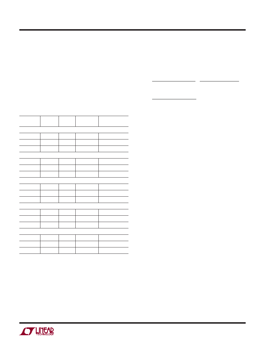
Table 1. Representative Buck-Boost Surface Mount Inductors
PART
NUMBER
VALUE
(μH)
DCR
(mΩ)
MAX DC
CURRENT (A)
SIZE (mm)
W
× L × H
CoilCraft (www.coilcraft.com)
MSS1048
2.2
7.2
8.4
10
× 10.3 × 4
MSS1260
2.2
12
13.9
12.3
× 12.3 × 6
SER1052
2.2
4
10
10.6
× 10.6 × 5.2
Toko (www.toko.com)
D106C
2.4
7.7
10
10.3
× 10.3 × 6.7
FDA1055
2.2
4.8
10.5
11.6
× 10.8 × 5.5
FDA1254
2.2
4.5
14.7
13.5
× 12.6 × 5.4
Cooper (www.cooperbussmann.com)
HCP0703
2.2
18
14
7
× 7.3 × 3
HCP0704
2.3
16.5
11.5
6.8
× 6.8 × 4.2
HC8
2.6
11.4
10
10.9
× 10.4 × 4
TDK (www.component.tdk.com)
VLF100040
2.2
7.9
8.2
9.7
× 10 × 4
RLF12560
2.7
4.5
12
13
× 13 × 6
VLF12060
2.7
6.4
10
11.7
× 12 × 6
Wurth (www.we-online.com)
744066
2.2
10.5
6.8
10
× 10 × 3.8
744355
2
8
13
13.2
× 12.8 × 6.2
744324
2.4
4.8
17
10.5
× 10.2 × 4.7
OUTPUT CAPACITOR SELECTION
A low ESR output capacitor should be utilized at the buck-
boost converter output in order to minimize output voltage
ripple. Multilayer ceramic capacitors are an excellent choice
as they have low ESR and are available in small footprints.
The capacitor should be chosen large enough to reduce the
output voltage ripple to acceptable levels. Neglecting the
capacitor ESR and ESL, the peak-to-peak output voltage
ripple can be calculated by the following formulas, where
f is the frequency in MHz, COUT is the capacitance in μF, L
is the inductance in μH, VIN is the input voltage in volts,
VOUT is the output voltage in volts. VP-P is the output
ripple in volts and ILOAD is the output current in amps.
C
OUT ≥
1
ΔV
P-P,BUCK 8 L f
2
V
IN –VOUT
()V
OUT
V
IN
F
()
C
OUT ≥
I
LOAD VOUT –VIN
()
ΔV
P-P,BOOST VOUT f
F
()
Given that the output current is discontinuous in boost
mode, the ripple in this mode will generally be much larger
than the magnitude of the ripple in buck mode.
INPUT CAPACITOR SELECTION
It is recommended that a low ESR ceramic capacitor with a
value of at least 47μF be located as close to VIN as possible.
In addition, the return trace from the pin to the ground
plane should be made as short as possible. It is important
to minimize any stray resistance from the converter to the
battery or other power sources. If cabling is required to
connect the LTC3113 to the battery or power supply, a higher
ESR capacitor or a series resistor with low ESR capacitor
in parallel with the low ESR capacitor may be needed to
damp out ringing caused by the cable inductance.
CAPACITOR VENDOR INFORMATION
Both the input bypass capacitors and output capacitors
used with the LTC3113 must be low ESR and designed
to handle the large AC currents generated by switching
converters. This is important to maintain proper functioning
of the IC and to reduce output ripple. Many modern low
voltage ceramic capacitors experience signicant loss in
capacitance from their rated value with increased DC bias
voltages. For example, it is not uncommon for a small
surface mount ceramic capacitor to lose 50% or more
of its rated capacitance when operated near its rated
voltage. As a result, it is sometimes necessary to use
a larger value capacitance or a capacitor with a higher
voltage rating than required in order to actually realize
the intended capacitance at the full operating voltage. For
details, consult the capacitor vendor’s curve of capacitance
versus DC bias voltage.
相關(guān)PDF資料 |
PDF描述 |
|---|---|
| LTC3113IFE#PBF | 16 A SWITCHING REGULATOR, 2000 kHz SWITCHING FREQ-MAX, PDSO20 |
| LTC3125EDCB#TRMPBF | SWITCHING REGULATOR, 1900 kHz SWITCHING FREQ-MAX, PDSO8 |
| LTC3127EDD#PBF | SWITCHING REGULATOR, PDSO10 |
| LTC3127EMSE#TRPBF | SWITCHING REGULATOR, PDSO12 |
| LTC3225EDDB-1#TRMPBF | 0.175 A SWITCHED CAPACITOR CONVERTER, 1500 kHz SWITCHING FREQ-MAX, PDSO10 |
相關(guān)代理商/技術(shù)參數(shù) |
參數(shù)描述 |
|---|---|
| LTC3113IFE#PBF | 功能描述:IC REG BUCK BOOST ADJ 3A 20TSSOP RoHS:是 類別:集成電路 (IC) >> PMIC - 穩(wěn)壓器 - DC DC 開關(guān)穩(wěn)壓器 系列:- 設(shè)計資源:Design Support Tool 標(biāo)準(zhǔn)包裝:1 系列:- 類型:升壓(升壓) 輸出類型:固定 輸出數(shù):1 輸出電壓:3V 輸入電壓:0.75 V ~ 2 V PWM 型:- 頻率 - 開關(guān):- 電流 - 輸出:100mA 同步整流器:是 工作溫度:-40°C ~ 85°C 安裝類型:表面貼裝 封裝/外殼:SOT-23-5 細(xì)型,TSOT-23-5 包裝:剪切帶 (CT) 供應(yīng)商設(shè)備封裝:TSOT-23-5 其它名稱:AS1323-BTTT-30CT |
| LTC3113IFE#TRPBF | 功能描述:IC REG BUCK BOOST ADJ 3A 20TSSOP RoHS:是 類別:集成電路 (IC) >> PMIC - 穩(wěn)壓器 - DC DC 開關(guān)穩(wěn)壓器 系列:- 設(shè)計資源:Design Support Tool 標(biāo)準(zhǔn)包裝:1 系列:- 類型:升壓(升壓) 輸出類型:固定 輸出數(shù):1 輸出電壓:3V 輸入電壓:0.75 V ~ 2 V PWM 型:- 頻率 - 開關(guān):- 電流 - 輸出:100mA 同步整流器:是 工作溫度:-40°C ~ 85°C 安裝類型:表面貼裝 封裝/外殼:SOT-23-5 細(xì)型,TSOT-23-5 包裝:剪切帶 (CT) 供應(yīng)商設(shè)備封裝:TSOT-23-5 其它名稱:AS1323-BTTT-30CT |
| LTC3115-1 | 制造商:LINEAR 制造商全稱:LINEAR 功能描述:40V, 2A Synchronous Buck-Boost DC/DC Converter |
| LTC3115EDHD-1#PBF | 功能描述:IC REG BUCK BST ADJ 1A/2A 16-DFN RoHS:是 類別:集成電路 (IC) >> PMIC - 穩(wěn)壓器 - DC DC 開關(guān)穩(wěn)壓器 系列:- 標(biāo)準(zhǔn)包裝:250 系列:- 類型:降壓(降壓) 輸出類型:固定 輸出數(shù):1 輸出電壓:1.2V 輸入電壓:2.05 V ~ 6 V PWM 型:電壓模式 頻率 - 開關(guān):2MHz 電流 - 輸出:500mA 同步整流器:是 工作溫度:-40°C ~ 85°C 安裝類型:表面貼裝 封裝/外殼:6-UFDFN 包裝:帶卷 (TR) 供應(yīng)商設(shè)備封裝:6-SON(1.45x1) 產(chǎn)品目錄頁面:1032 (CN2011-ZH PDF) 其它名稱:296-25628-2 |
| LTC3115EDHD-1#TRPBF | 功能描述:IC REG BUCK BST ADJ 1A/2A 16-DFN RoHS:是 類別:集成電路 (IC) >> PMIC - 穩(wěn)壓器 - DC DC 開關(guān)穩(wěn)壓器 系列:- 設(shè)計資源:Design Support Tool 標(biāo)準(zhǔn)包裝:1 系列:- 類型:升壓(升壓) 輸出類型:固定 輸出數(shù):1 輸出電壓:3V 輸入電壓:0.75 V ~ 2 V PWM 型:- 頻率 - 開關(guān):- 電流 - 輸出:100mA 同步整流器:是 工作溫度:-40°C ~ 85°C 安裝類型:表面貼裝 封裝/外殼:SOT-23-5 細(xì)型,TSOT-23-5 包裝:剪切帶 (CT) 供應(yīng)商設(shè)備封裝:TSOT-23-5 其它名稱:AS1323-BTTT-30CT |
發(fā)布緊急采購,3分鐘左右您將得到回復(fù)。