- 您現(xiàn)在的位置:買賣IC網(wǎng) > PDF目錄44979 > LT1740-7Z (POWER-ONE INC) 1-OUTPUT 500 W AC-DC REG PWR SUPPLY MODULE PDF資料下載
參數(shù)資料
| 型號: | LT1740-7Z |
| 廠商: | POWER-ONE INC |
| 元件分類: | 電源模塊 |
| 英文描述: | 1-OUTPUT 500 W AC-DC REG PWR SUPPLY MODULE |
| 文件頁數(shù): | 10/32頁 |
| 文件大?。?/td> | 1000K |
| 代理商: | LT1740-7Z |
第1頁第2頁第3頁第4頁第5頁第6頁第7頁第8頁第9頁當(dāng)前第10頁第11頁第12頁第13頁第14頁第15頁第16頁第17頁第18頁第19頁第20頁第21頁第22頁第23頁第24頁第25頁第26頁第27頁第28頁第29頁第30頁第31頁第32頁
BCD20023 Rev. AA, 3-Sep-2008
Page 18 of 32
www.power-one.com
T Series Data Sheet
500 Watt AC-DC Converters
Different Configurations and Applications
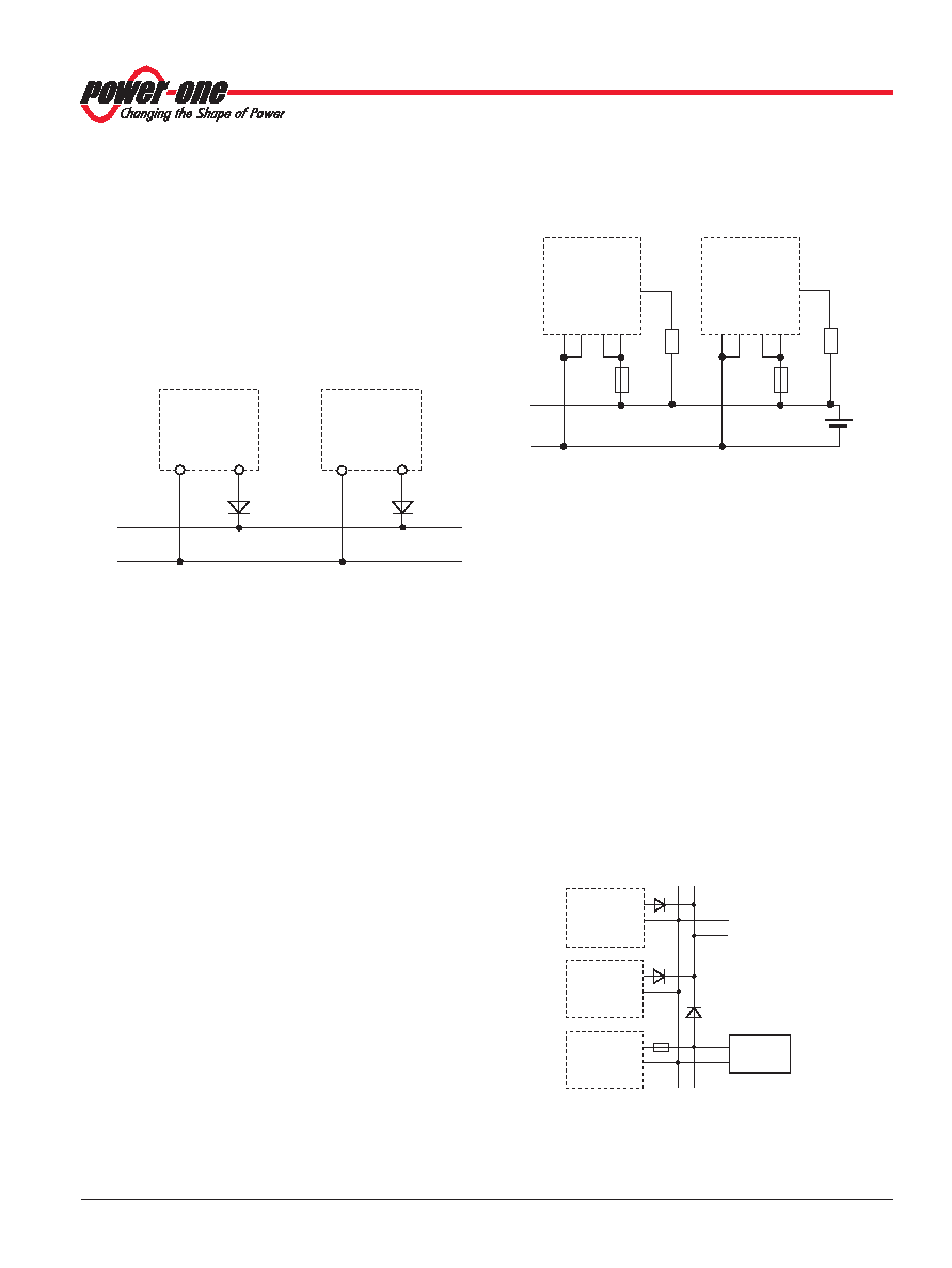
Power Boosting, Redundant Configuration,
Hot Swap
For redundant configurations the outputs should be decoupled
by ORing diodes, protecting the DC-bus in case of an internal
short circuit at the output of one converter.
Decoupling can also be done using appropriate fuses in the
output path of each converter. If the battery voltage has to be
monitored, choose option D.
+
–
Converter
Vo–
Vo+
Vo–
Vo+
06077a
+
–
Vo–
Vo+
Vo–
Vo+
LT/UTxx40
HC–
HC+
HC–
Fuse
+
–
D set
R
43k2
R
43k2
D set
(21k5)
06079a
Fig. 32
Redundant configuration without battery back-up
Fig. 33
T xx40 with battery back-up. Power Down signal monitoring
the battery voltage.
battery-buffered bus. Should however the converter already be
connected, when the battery is switched to the bus, the resulting
charge current will not be limited. To avoid having the fuse blow or
a possible arc across the circuit breaker, the battery charger
ORing diodes provide reverse polarity protection with no
reverse current in case of hot plug-in, but have the
disadvantage of some forward voltage drop.
For battery applications, decoupling with fuses is recom-
mended, since the voltage drop over the diodes would
decrease the battery voltage. In case of an internal short circuit
of a converter, the battery will deliver a very large current
causing the respective fuse to blow. The fuse should be
mounted in the positive power path of the converter, since the
monitoring signals are referenced to the negative path. The
fuse type should be suitable for DC application having a
current rating of 20 A or more with high breaking capability,
e.g., Littlefuse, series 314.
To enable hot plug-in in systems decoupled with fuses, the T
Series converters are fitted with an NTC resistor, limiting the
reverse current flowing into the discharged output capacitors
(see Functional Description).
For this purpose HC+ (pin 16) and HC– (pin 18) have to be
connected to Vo+ and Vo– respectively; see fig. 33. Since pins
16 and 18 are leading pins, the output capacitors are
precharged through the internal NTC resistor, before any other
pin makes contact. This protects the connector and prevents
the DC bus voltage from dropping during hot plug-in. Hot swap
should be done gently. Subsequent hot-swap actions should
be avoided. After disconnecting an operating converter, it
should be cooled down prior to reconnecting to the bus to
avoid damage of the fuse or the converter.
Note: The internal NTC limits the reverse charge current flowing
into the output capacitors, when the converter is plugged into a
should be powered by the mains prior to connecting the battery.
With ORing diodes, no reverse charge current flows from the
power bus into the output capacitors.
Battery Size and Ripple Current
Some consideration should be given to the battery size.
According to VDE 0510 part 2, the low frequency ripple current
of the floating charge current should not exceed 5 A per 100 Ah
capacity (0.05 C). The power factor corrected single step
conversion of the line input voltage to the low DC output
voltage generates a ripple voltage at the output of twice the
input frequency, causing a ripple current into the connected
battery.
T1701/1702
Vo: 56 V
T1701/1702
Vo: 56 V
T1740-7D
Vo range:
50.5...56 V
Battery
+
–
Load
06081a
Fig. 34
Configuration for a larger system with only a small battery
相關(guān)PDF資料 |
PDF描述 |
|---|---|
| LT1241MJ8 | 1 A SWITCHING CONTROLLER, 500 kHz SWITCHING FREQ-MAX, CDIP8 |
| LT1245MJ8 | 1 A SWITCHING CONTROLLER, 500 kHz SWITCHING FREQ-MAX, CDIP8 |
| LT1241CJ8 | 1 A SWITCHING CONTROLLER, 500 kHz SWITCHING FREQ-MAX, CDIP8 |
| LT1242CJ8 | 1 A SWITCHING CONTROLLER, 500 kHz SWITCHING FREQ-MAX, CDIP8 |
| LT1241IN8#TRPBF | SWITCHING CONTROLLER, 500 kHz SWITCHING FREQ-MAX, PDIP8 |
相關(guān)代理商/技術(shù)參數(shù) |
參數(shù)描述 |
|---|---|
| LT1743 | 制造商:未知廠家 制造商全稱:未知廠家 功能描述:Optoelectronic |
| LT1750 | 制造商:Pulse 功能描述:LAN,E/C,2000V - Bulk |
| LT1754ET | 制造商:Linear Technology 功能描述: |
| LT1761 | 制造商:LINER 制造商全稱:Linear Technology 功能描述:45V VIN, Micropower, Low Noise, 100mA Low Dropout, Linear Regulator |
| LT1761_1 | 制造商:LINER 制造商全稱:Linear Technology 功能描述:100mA, Low Noise,LDO Micropower Regulators in SOT-23 |
發(fā)布緊急采購,3分鐘左右您將得到回復(fù)。