- 您現在的位置:買賣IC網 > PDF目錄44982 > LT1740-7DB1 (POWER-ONE INC) 1-OUTPUT 550 W AC-DC REG PWR SUPPLY MODULE PDF資料下載
參數資料
| 型號: | LT1740-7DB1 |
| 廠商: | POWER-ONE INC |
| 元件分類: | 電源模塊 |
| 英文描述: | 1-OUTPUT 550 W AC-DC REG PWR SUPPLY MODULE |
| 封裝: | CASE T01, MODULE |
| 文件頁數: | 3/33頁 |
| 文件大?。?/td> | 838K |
| 代理商: | LT1740-7DB1 |
第1頁第2頁當前第3頁第4頁第5頁第6頁第7頁第8頁第9頁第10頁第11頁第12頁第13頁第14頁第15頁第16頁第17頁第18頁第19頁第20頁第21頁第22頁第23頁第24頁第25頁第26頁第27頁第28頁第29頁第30頁第31頁第32頁第33頁
Rugged Environment
AC-DC Converters >100 Watt
T Series
Edition 4/4.99
11/33
MELCHER
The Power Partners.
– In output voltage regulation mode the T unit can be oper-
ated within the full temperature range –25...71
°C.
– In output power or current limitation mode the max. ambi-
ent temperature
TA should not exceed 65
°C with free air
convection cooling.
Output current limitation (Battery Charger Version)
The output of the T units is fully protected against continu-
ous short circuit. The maximum constant current is limitted
to
Io L (see table: Electrical output data). As the LED indicat-
ing the system status are driven from the output voltage, in
short circuit all LED‘s will switch off.
Output voltage regulation (Battery Charger Version)
In normal operating mode (unit neither in power limitation
nor in current limitation) the output is regulated by a voltage
feedback loop. It is adjustet to
Uo set and can be set by the
cell voltage selector switch to the appropriate float charge
voltage of the battery.
The battery charger version features a control input (pin 28)
for remote output voltage adjustment either by a voltage
source, a temperature sensor or an external potential di-
vider (see:
Output voltage control via Inhibit/Ucr remote
control input). For fine tuning, the units are fitted with a trim
potentiometer accessible from the rear of the connector.
The output voltage relates to the output current and the in-
put voltage which ensures automatic current sharing opera-
tion without further precautions when several units are con-
nected in parallel. An increase in output current and a de-
crease in input voltage decreases the output voltage, ac-
cording to the formula:
Uo
≈ U
o set tol + (0.5 – Io/Io nom) DUo I
+ (
Ui – Ui nom)/100 V DUo U
Note: Units with different output voltage regulation e.g.
less output current dependency are available upon request.
1.1%
0.55%
0
–0.9%
0.01
0.5
1
Io/Io nom
U
o
Load
regulation
05046
Uo set
Fig. 15
Typical output voltage versus input voltage and output
current of the LT 1740.
Output power limitation (Battery Charger Version)
All battery charger versions feature an output power limita-
tion mode where the output power is kept constant from
2.35 V/cell (for lead acid batteries) to 1.6 V/cell. This pro-
vides better starting up capabilities for power systems in-
cluding switched mode power supplies connected to the
DC bus when the battery is charged.
The maximum input current is limited to
Ii L. At lower input
voltage
Ui red, the maximum output power is limited to:
Po
≈ h U
i red Ii L
(
h = efficiency
≈ 90%)
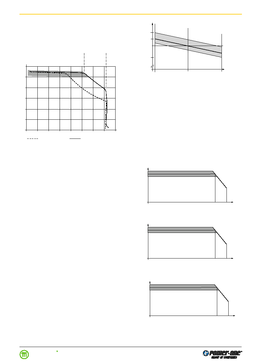
Typical output characteristics according to type
Io
0
Uo
26.7 V
06065
15 A
20 A
28.25 V
25.25 V
19 V
Io
0
Uo
54.5 V
06066
10 A
14.5 A
56.5 V
50.5 V
38 V
Fig. 17
Typical output voltage versus output current of UT/LT 1740
Fig. 16
Typical output voltage versus output current of UT/LT 1240
Output Characteristics (Battery Charger Version)
The battery charger versions T 1240/T 1740/T 1840 series
can be operated in 3 different modes:
– Output voltage regulation
– Output power limitation
– Output current limitation
0
2
4
6
8
10
12
14
16
60
50
40
30
20
10
0
Io [A]
Uo [V]
Ui = 110 Vrms
Ui = 230 Vrms
Output
voltage
regulation
Output
power
limitation
Output
current
limitation
05045
Fig. 14
Output characteristics LT 1740-7
Io
0
Uo
40.88 V
06067
11 A
16 A
42.4 V
37.9 V
28.5 V
Fig. 18
Typical output voltage versus output current of
LT 1840
相關PDF資料 |
PDF描述 |
|---|---|
| LT1240-7DZ | 1-OUTPUT 400 W AC-DC REG PWR SUPPLY MODULE |
| LT1201-7DB1 | 1-OUTPUT 400 W AC-DC REG PWR SUPPLY MODULE |
| LT1701-7DF | 1-OUTPUT 550 W AC-DC REG PWR SUPPLY MODULE |
| LT1240-7DF | 1-OUTPUT 400 W AC-DC REG PWR SUPPLY MODULE |
| LT1740-7DFB1 | 1-OUTPUT 550 W AC-DC REG PWR SUPPLY MODULE |
相關代理商/技術參數 |
參數描述 |
|---|---|
| LT1740-7DZ | 制造商:Power-One 功能描述:ACDC - Bulk |
| LT1740-7Z | 功能描述:AC-DC BATTERY CHARGER 54.5V 10A RoHS:否 類別:電源 - 外部/內部(非板載) >> AC DC 轉換器 系列:* 產品培訓模塊:MP Modular-Configurable AC-DC Power Supply 特色產品:Configurable Power Supplies 標準包裝:1 系列:MP |
| LT1743 | 制造商:未知廠家 制造商全稱:未知廠家 功能描述:Optoelectronic |
| LT1750 | 制造商:Pulse 功能描述:LAN,E/C,2000V - Bulk |
| LT1754ET | 制造商:Linear Technology 功能描述: |
發(fā)布緊急采購,3分鐘左右您將得到回復。