- 您現(xiàn)在的位置:買賣IC網(wǎng) > PDF目錄44982 > LT1701-7DF (POWER-ONE INC) 1-OUTPUT 550 W AC-DC REG PWR SUPPLY MODULE PDF資料下載
參數(shù)資料
| 型號: | LT1701-7DF |
| 廠商: | POWER-ONE INC |
| 元件分類: | 電源模塊 |
| 英文描述: | 1-OUTPUT 550 W AC-DC REG PWR SUPPLY MODULE |
| 封裝: | CASE T01, MODULE |
| 文件頁數(shù): | 15/33頁 |
| 文件大?。?/td> | 838K |
| 代理商: | LT1701-7DF |
第1頁第2頁第3頁第4頁第5頁第6頁第7頁第8頁第9頁第10頁第11頁第12頁第13頁第14頁當(dāng)前第15頁第16頁第17頁第18頁第19頁第20頁第21頁第22頁第23頁第24頁第25頁第26頁第27頁第28頁第29頁第30頁第31頁第32頁第33頁
T Series
AC-DC Converters >100 Watt
Rugged Environment
Edition 4/4.99
22/33
MELCHER
The Power Partners.
Battery Size and Ripple Current
Some consideration should be given to the selection of the
battery size. According to VDE 0510 part 2, the low fre-
quency ripple current of the floating charge current should
not exceed 5 Arms per 100 Ah capacity (0.05 C). The power
factor corrected single step conversion of the line input volt-
age to the low DC output voltage generates a ripple voltage
at the output of twice the input frequency, causing a ripple
current into the connected battery.
For systems where only a small battery back-up time is re-
quired, battery charging by one T unit may be sufficient (see
also fig. below).
For systems with more than one T unit charging the battery
please refer to the chapter:
Back Plane.
T 1000
Uo: 56.0 V
T 1000
Uo: 56.0 V
T 1700-7D
Uo range
50.5...56.0 V
Battery
+
–
Load
06081
Fig. 41
Alternative configuration for a larger system with a small
battery
If the ripple current is too high e.g. in the case of a smaller
battery to be connected to the system, a large capacitor
with low impedance can be connected in parallel with the
battery. Another possibility is to connect an additional im-
pedance to the battery line, e.g. a choke or an NTC-resistor
(30 A or 60 A chokes are available on request. Please con-
sult Melcher's application center). Further considerations
for the selection of battery size include desired back-up
time, required battery life, temperature range and maxi-
mum permissible discharge current. Consult the manufac-
turers of lead-acid batteries for the final selection.
Caution: Lead-acid batteries can generate certain
amounts of H2 and O2 gas which can form explosive gas
mixtures. Sufficient ventilation must be provided in bat-
tery cabinets and installation rooms.
Local regulations must be observed. Further information
about designing battery systems is contained in VDE 0510,
part 2.
Combination of T Units and CQ Units without Battery
In a complete power system consisting of two or more T
units in parallel combined with Melcher CQ units it may be
desirable to have one common signal indicating the status
of the whole system.
The Melcher CQ units provide a galvanically isolated signal
Out OK. To obtain a logic AND all CQ Out OK signals
should be connected in series (see also fig.:
Wired AND of
galvanically isolated open collector signals). Out OK– of the
first CQ unit should be connected to Vo–, Out OK+ of the
last CQ unit should be connected to pin Sys In of one of the
T units. Sys Out should be connected to Sys In of the next T
unit. If one of the units fails (T or CQ ) it will be indicated by
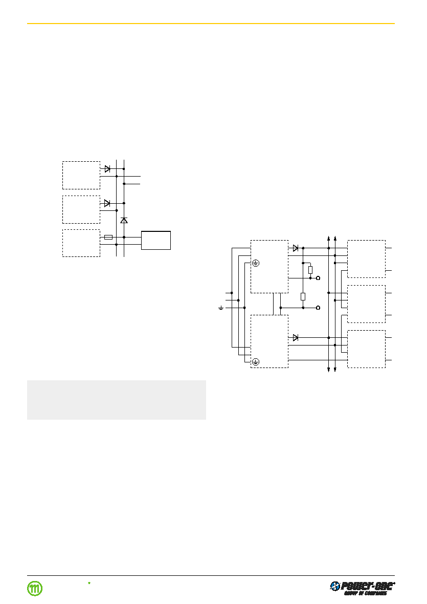
the overall System Good (see fig. below).
If in a system with 2 redundant T units Power Down is de-
sired as one common signal, independent of a possible fail-
ure of one of the two T units, simply interconnect the D pins
of the two T units. In this way Power Down only becomes
active if both T units fail which would result in the bus volt-
age falling (see fig. below).
Note: Consider the behaviour of the signalling in a system
with decoupling diodes or fuses in the case of a T-failure,
with the secondary in short circuit.
Fig. 42
Monitoring of overall System Good and Power Bus Down
in a redundant system
+
–
Out OK–
Out OK+
+
–
CQ 1
+
–
Out OK–
Out OK+
+
–
CQ 2
+
–
Out OK–
Out OK+
+
–
CQ 3
P
N
Vo+
Vo–
T
1701
P
N
Vo+
Vo–
P
N
Sys Out
Sys In
D
T
1701
Sys In
D
Overall
System
Good
Power
Down
+
–
R
06082
相關(guān)PDF資料 |
PDF描述 |
|---|---|
| LT1240-7DF | 1-OUTPUT 400 W AC-DC REG PWR SUPPLY MODULE |
| LT1740-7DFB1 | 1-OUTPUT 550 W AC-DC REG PWR SUPPLY MODULE |
| LT1840-7 | 1-OUTPUT 450 W AC-DC REG PWR SUPPLY MODULE |
| LT1240-7DB1 | 1-OUTPUT 400 W AC-DC REG PWR SUPPLY MODULE |
| LT1701-7DFB1 | 1-OUTPUT 550 W AC-DC REG PWR SUPPLY MODULE |
相關(guān)代理商/技術(shù)參數(shù) |
參數(shù)描述 |
|---|---|
| LT1702-7 | 功能描述:AC-DC BATTERY CHARGER 48V 11A RoHS:否 類別:電源 - 外部/內(nèi)部(非板載) >> AC DC 轉(zhuǎn)換器 系列:* 產(chǎn)品培訓(xùn)模塊:MP Modular-Configurable AC-DC Power Supply 特色產(chǎn)品:Configurable Power Supplies 標(biāo)準(zhǔn)包裝:1 系列:MP |
| LT170A | 制造商:未知廠家 制造商全稱:未知廠家 功能描述:Linear Hall-Effect Sensor |
| LT170E2 | 制造商:未知廠家 制造商全稱:未知廠家 功能描述:LT170E2 |Data Sheet |
| LT170Z | 制造商:SEOUL 制造商全稱:Seoul Semiconductor 功能描述:GREEN OVAL LAMP LED |
| LT171 | 制造商:SEOUL 制造商全稱:Seoul Semiconductor 功能描述:RED LAMP LED |
發(fā)布緊急采購,3分鐘左右您將得到回復(fù)。