- 您現(xiàn)在的位置:買(mǎi)賣(mài)IC網(wǎng) > PDF目錄44967 > LSM-5/16-D12-C (MURATA POWER SOLUTIONS INC) 1-OUTPUT DC-DC REG PWR SUPPLY MODULE PDF資料下載
參數(shù)資料
| 型號(hào): | LSM-5/16-D12-C |
| 廠商: | MURATA POWER SOLUTIONS INC |
| 元件分類(lèi): | 電源模塊 |
| 英文描述: | 1-OUTPUT DC-DC REG PWR SUPPLY MODULE |
| 封裝: | ROHS COMPLIANT, SMT-6 |
| 文件頁(yè)數(shù): | 9/12頁(yè) |
| 文件大?。?/td> | 381K |
| 代理商: | LSM-5/16-D12-C |
Where VO is the desired output voltage.
The LSM-T/16-D12 xed resistance values to set the output values are:
VO
0.7525V
1.0V
1.2V
1.5V
1.8V
2.5V
3.3V
5.0V
RT (k
Ω) Open 41.424 22.46 13.05 9.024 5.009 3.122 1.472
CAUTION: To retain proper regulation, do not exceed the 5 Volt output.
Voltage Trim
The LSM-T/16-D12 may also be trimmed using an external voltage applied
between the Trim Input and Output Common. Be aware that the internal “l(fā)oad”
impedance looking into trim pin is approximately 5k
Ω. Therefore, you may
have to compensate for this in the source resistance of your external voltage
reference.
The equation for this voltage adjustment is:
VTRIM = 0.7 – (0.0667 × (VO – 0.7525))
The LSM-T/16-D12 xed trim voltages to set the output voltage are:
VO
0.7525V
1.0V
1.2V
1.5V
1.8V
2.5V
3.3V
5.0V
VT (V)
Open
0.6835 0.670
0.650
0.630
0.583
0.530 0.4166
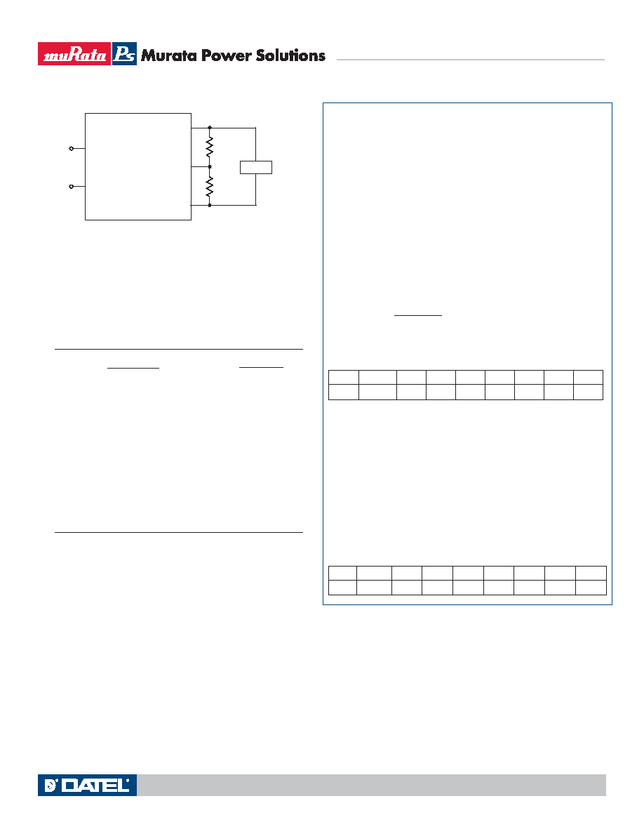
Trim
Down
Trim
Up
LOAD
+INPUT
COMMON
+OUTPUT
TRIM
COMMON
Where: VO = Desired Output Voltage
VO
NOM = Nominal Output Voltage
UP
VO – VO
NOM
RT
(k ) =
5.509
– X
DOWN
VO
NOM – VO
RT
(k ) =
– X
7.87(VO – 0.7)
LSM-0.75/16-D12:
X = 0.909
LSM-1/16-D12:
X = 11.5
LSM-1.2/16-D12:
X = 19.1
LSM-1.5/16-D12:
X = 27.4
LSM-1.8/16-D12:
X = 16.9
LSM-2/16-D12:
X = 21.5
LSM-2.5/16-D12:
X = 18.2
LSM-3.3/16-D12:
X = 13.7
LSM-5/16-D12:
X = 9.09
“T” Model LSM-T/16-D12
This version of the LSM 16A series offers a special output voltage trimming
feature which is fully compatible with competitive units. The output voltage
may be varied from 0.75 to 5 Volts using a single external trim-up resistor con-
nected from the Trim input to Output Common. If no trim resistor is attached
(Trim pin open), the output is 0.7525 Volts.
The trim may also be adjusted using an external reference voltage con-
nected to the Trim input.
As with other trim adjustments, use a 1% metal lm precision resistor with
low temperature coefcient (±100 ppm/°C or less) mounted close to the con-
verter with short leads. Also be aware that the output accuracy is ±2% (typical)
therefore you may need to vary this resistance slightly to achieve your desired
output setting.
The resistor trim up equation for the LSM-T/16-D12 is as follows:
Figure 7. Trim Connections Using Fixed Resistors
The equations below can be starting points for selecting specic trim-resistor
values. Recall, untrimmed devices are guaranteed to be ±1.25% accurate.
Adjustment beyond the specied ±10% adjustment range is not recom-
mended. When using trim in combination with Remote Sense, the maximum
rated power must not be exceeded (see Remote Sense).
Trim Equations
Note: Resistor values are in k
Ω. Accuracy of adjustment is subject
to tolerances of resistors and factory-adjusted, initial output accuracy.
VO = desired output voltage. VONOM = nominal output voltage.
UP
VO – 0.7525
RT
( ) =
10500
– 1000
LSM-16A D12 Models
Non-Isolated, 13-80W SMT DC/DC Converters
MDC_LSM 16A D12 Models.A05 Page 6 of 12
Technical enquiries email: sales@murata-ps.com, tel: +1 508 339 3000
www.murata-ps.com
相關(guān)PDF資料 |
PDF描述 |
|---|---|
| LSM-2.5/16-D12-C | 1-OUTPUT DC-DC REG PWR SUPPLY MODULE |
| LSM-1.8/16-D12-C | 1-OUTPUT DC-DC REG PWR SUPPLY MODULE |
| LSM-3.3/16-D12-C | 1-OUTPUT DC-DC REG PWR SUPPLY MODULE |
| LSM2-T/10-D12G-C | 1-OUTPUT 33 W DC-DC REG PWR SUPPLY MODULE |
| LSM2-T/6-W3N-C | 1-OUTPUT 19.8 W DC-DC REG PWR SUPPLY MODULE |
相關(guān)代理商/技術(shù)參數(shù) |
參數(shù)描述 |
|---|---|
| LSM535 | 制造商:MICROSEMI 制造商全稱(chēng):Microsemi Corporation 功能描述:5 Amp Schottky Rectifier |
| LSM535G | 制造商:未知廠家 制造商全稱(chēng):未知廠家 功能描述:Schottky Rectifier |
| LSM535G/TR13 | 制造商:Microsemi Corporation 功能描述:5.0A, 35V, VF=0.52V - Tape and Reel 制造商:Microsemi Corporation 功能描述:DIODE SCHOTTKY 5A 35V SMCG |
| LSM535GE3/TR13 | 制造商:Microsemi Corporation 功能描述:5.0A, 35V, VF=0.52V - Tape and Reel 制造商:Microsemi Corporation 功能描述:DIODE SCHOTTKY 5A 35V SMCG |
| LSM535J | 制造商:未知廠家 制造商全稱(chēng):未知廠家 功能描述:Schottky Rectifier |
發(fā)布緊急采購(gòu),3分鐘左右您將得到回復(fù)。