- 您現(xiàn)在的位置:買(mǎi)賣(mài)IC網(wǎng) > PDF目錄44924 > LS4601-9RD5B1 (POWER-ONE INC) 1-OUTPUT 100 W AC-DC PWR FACTOR CORR MODULE PDF資料下載
參數(shù)資料
| 型號(hào): | LS4601-9RD5B1 |
| 廠商: | POWER-ONE INC |
| 元件分類(lèi): | 電源模塊 |
| 英文描述: | 1-OUTPUT 100 W AC-DC PWR FACTOR CORR MODULE |
| 封裝: | METAL, CASE S02, MODULE |
| 文件頁(yè)數(shù): | 15/27頁(yè) |
| 文件大?。?/td> | 599K |
| 代理商: | LS4601-9RD5B1 |
第1頁(yè)第2頁(yè)第3頁(yè)第4頁(yè)第5頁(yè)第6頁(yè)第7頁(yè)第8頁(yè)第9頁(yè)第10頁(yè)第11頁(yè)第12頁(yè)第13頁(yè)第14頁(yè)當(dāng)前第15頁(yè)第16頁(yè)第17頁(yè)第18頁(yè)第19頁(yè)第20頁(yè)第21頁(yè)第22頁(yè)第23頁(yè)第24頁(yè)第25頁(yè)第26頁(yè)第27頁(yè)
Cassette Style
100 Watt AC-DC Converters
S Series PFC
Edition 01/01.2001
22/27
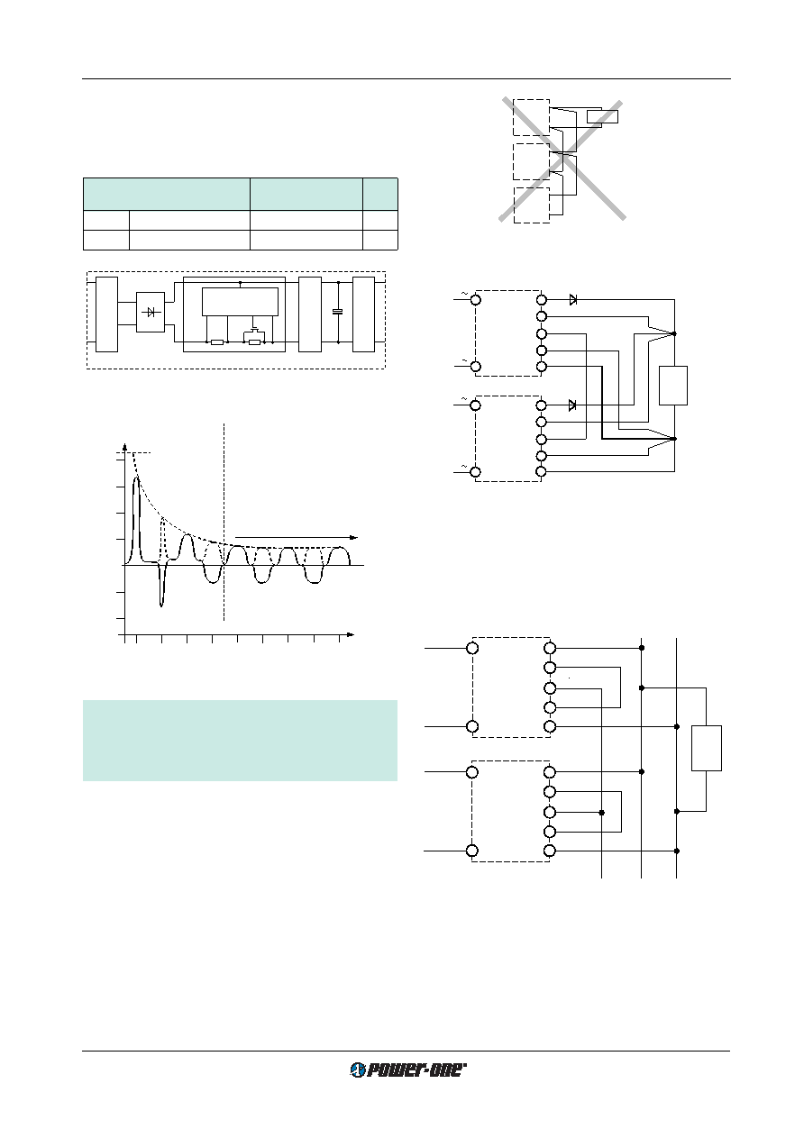
Fig. 34
Paralleling of single output units using option T with the
sense lines connected at the load
Load
max. 5 units in parallel connection
+
–
Power bus
Module
Vo2–
Vo2+
Vo1–
Vo1+
T
Module
Vo2–
Vo2+
Vo1–
Vo1+
T
11037
Load
1
2
3
LS 4000
S+
Vo+
Vo–
S–
N
P
T
LS 4000
N
P
S+
Vo+
Vo–
S–
T
1
max. 5 units connected in parallel
11011
1 Leads should have equal length and cross sections and should
run in the same cable loom.
2 Diodes recommended in redundant operation only
3 DC common point
Fig. 35
Paralleling of double output units using option T with
Power bus.
E Inrush Current Limitation
The converters may be supplemented by an electronic cir-
cuit (option E, replacing the standard built-in NTC) to
achieve an enhanced inrush current limiting function.
Table 17: Inrush current characteristics with option E
Characteristics
LS
Unit
Ui = 230 V AC
typ
max
Iinr p
Peak inrush current
–
25.3
A
tinr
Inrush current duration
35
50
ms
15
Ii [A]
10
5
0
–5
–10
0
20
40
60
80
t [ms]
tinr
Capacitor
Ci
fully charged
Normal operation
(FET fully conducting)
20
10
50
70
30
11002
Fig. 32
Inrush current with option E, Ui = 230 V AC, Po = Po nom
Precaution:
Subsequent switch-on cycles at start-up are limited to
max. 10 cycles during the rst 20 seconds (cold unit)
and at continuing on/off (
TC =95°C) max. 1 cycle every
8sec.
Vo+
Vo–
Vo+
Vo–
Load
Vo+
Vo–
11003
Input
Filter
Control
Converter
FET
Ci
RI
RS
Rectifier
PFC
-
Control
11
0
1
Fig. 31
Option E block diagram
T Current Sharing
This option ensures that the output currents are approxi-
mately shared between all paralleled modules and in-
creases system reliability. To use this facility, simply inter-
connect the T pins of all modules and make sure, that
pin 14, the S– pin (S 4000) or the Vo1– pins (S 5000) are
also connected together. The load leads should have equal
length and cross section to ensure equal voltage drops. Not
more than 5 units should be connected in parallel. If output
voltage adjustment is requested we strongly recommend to
use the R-input instead of option P, as with option P the re-
quired setting accuracy is difcult to achieve. The output
voltages must be individually set prior to paralleling to
within a tolerance of 1...2% or the R pins should be con-
nected together.
Fig. 33
An example of poor wiring for connection in parallel
相關(guān)PDF資料 |
PDF描述 |
|---|---|
| LS4601-9RD5B2 | 1-OUTPUT 100 W AC-DC PWR FACTOR CORR MODULE |
| LS4601-9RD8B2 | 1-OUTPUT 100 W AC-DC PWR FACTOR CORR MODULE |
| LS5320-7EPD7B1 | 2-OUTPUT 100 W AC-DC PWR FACTOR CORR MODULE |
| LS5320-7EPD8B1 | 2-OUTPUT 100 W AC-DC PWR FACTOR CORR MODULE |
| LS5320-7ERD1B2 | 2-OUTPUT 100 W AC-DC PWR FACTOR CORR MODULE |
相關(guān)代理商/技術(shù)參數(shù) |
參數(shù)描述 |
|---|---|
| LS460-RH | 功能描述:INVERTER 10.8-13.2V IN 1300V OUT RoHS:是 類(lèi)別:光電元件 >> 反相器 系列:- 標(biāo)準(zhǔn)包裝:100 系列:- 輸入電壓:6.0V 輸出:900V 類(lèi)型:用于 CCFL 和 UV 燈的逆變器 尺寸/尺寸:2.34" L x 0.35" W x 0.35" H(59.5mm x 9mm x 8.9mm) 安裝類(lèi)型:底座安裝 |
| LS46200A | 制造商:T&B 功能描述:_ |
| LS470M2H-22253S | 制造商:Surge Components Inc 功能描述:CAP ALUMINUM 47UH 500V 22 X 25 |
| LS-471M2C---2230S | 制造商:Surge Components Inc 功能描述:CAP ALUM 470UF 160V ?20% 2000LHRS 22 X 30 - Bulk |
| LS-471M2C---2525S | 制造商:Surge Components Inc 功能描述:CAP ALUM 470UF 160V ?20% 2000LHRS 25 X 25 - Bulk |
發(fā)布緊急采購(gòu),3分鐘左右您將得到回復(fù)。