- 您現(xiàn)在的位置:買賣IC網(wǎng) > PDF目錄44826 > LS2540-7RDD (POWER-ONE INC) 2-OUTPUT AC-DC REG PWR SUPPLY MODULE PDF資料下載
參數(shù)資料
| 型號(hào): | LS2540-7RDD |
| 廠商: | POWER-ONE INC |
| 元件分類: | 電源模塊 |
| 英文描述: | 2-OUTPUT AC-DC REG PWR SUPPLY MODULE |
| 封裝: | HEAT SINK, METAL, CASE S02, MODULE |
| 文件頁(yè)數(shù): | 18/33頁(yè) |
| 文件大?。?/td> | 438K |
| 代理商: | LS2540-7RDD |
第1頁(yè)第2頁(yè)第3頁(yè)第4頁(yè)第5頁(yè)第6頁(yè)第7頁(yè)第8頁(yè)第9頁(yè)第10頁(yè)第11頁(yè)第12頁(yè)第13頁(yè)第14頁(yè)第15頁(yè)第16頁(yè)第17頁(yè)當(dāng)前第18頁(yè)第19頁(yè)第20頁(yè)第21頁(yè)第22頁(yè)第23頁(yè)第24頁(yè)第25頁(yè)第26頁(yè)第27頁(yè)第28頁(yè)第29頁(yè)第30頁(yè)第31頁(yè)第32頁(yè)第33頁(yè)
S Series Data Sheet
100 Watt AC-DC and DC-DC Converters
APR 26, 2006 revised to SEP 25, 2006
Page 25 of 33
www.power-one.com
Load
1
2
S+
Vo+
Vo–
S–
Vi+
Vi–
T
Vi+
Vi–
S+
Vo+
Vo–
S–
T
1
Max. 5 converters in parallel connection
11036_012006
Converter
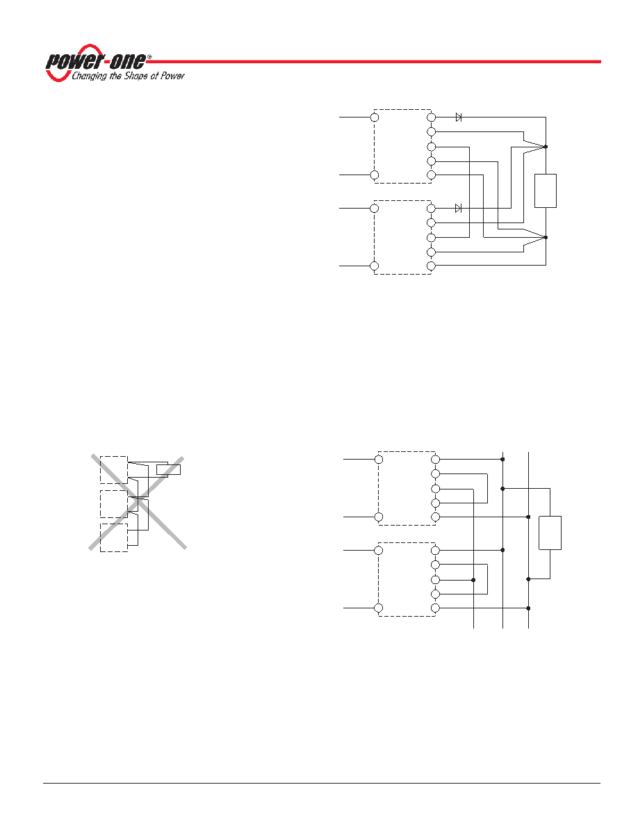
Fig. 29
Paralleling of single-output models using option T with the
sense lines connected at the load
1 Leads should have equal length and cross sections and should
run in the same cable loom.
2 Diodes for redundant operation.
Vo+
Vo–
Vo+
Vo–
Load
Vo+
Vo–
11003_102005
Fig. 28
An example of poor wiring for connections in parallel
(unequal length of load lines)
Option T: Current Sharing
This option ensures that the output currents are
approximately shared between all paralleled converters,
hence increasing system reliability. To use this facility,
simply interconnect the T pins of all converters and make
sure that the reference pins for the T-pin (S- for the S1000
or Vo1– for S2000) are also connected together. The load
lines should have equal length and cross section to ensure
equal voltage drops. Not more than 5 converters should be
connected in parallel. The R-pins should be left in an open-
circuit condition. If not, prior to paralleling the Vo1 outputs
should be individually adjusted within 1 to 2%. Parallel
connection
of
converters
with
option
P
is
not
recommended.
Option P: Potentiometer
The potentiometer allows for an output voltage adjustment
in the range of +10/–60% of Vo nom. It is accessible
through a hole in the front cover. This feature enables
compensation of voltage drops across the connector and
wiring. Option P is not recommended if models are
connected in parallel.
In double-output models both outputs are influenced by the
potentiometer setting. If option P is fitted, the R-pin 16 is
not connected.
Note: If the output voltage is increased above Vo nom via the
R-input control, option P setting, remote sensing, or option T,
the output current(s) should be reduced accordingly so that
Po nom is not exceeded.
Load
Max. 5 converters in parallel connection
+–
Power bus
Vo2–
Vo2+
Vo1–
Vo1+
T
Vo2–
Vo2+
Vo1–
Vo1+
T
Converter
11037_012006
Fig. 30
Paralleling of double output models with the outputs
connected in series, and using option T in an application
with a power bus. Note that the signal at the T-pins is
referenced to Vo1-.
相關(guān)PDF資料 |
PDF描述 |
|---|---|
| LS2660-7EPD3TB1 | 2-OUTPUT 100 W AC-DC REG PWR SUPPLY MODULE |
| LS2660-7EPD5 | 2-OUTPUT AC-DC REG PWR SUPPLY MODULE |
| LS2660-7EPD7 | 2-OUTPUT AC-DC REG PWR SUPPLY MODULE |
| LS2660-7EPD8TB1 | 2-OUTPUT 100 W AC-DC REG PWR SUPPLY MODULE |
| LS2660-7RD0 | 2-OUTPUT AC-DC REG PWR SUPPLY MODULE |
相關(guān)代理商/技術(shù)參數(shù) |
參數(shù)描述 |
|---|---|
| LS2540-9ER | 制造商:Power-One 功能描述:ACDC - Bulk |
| LS2543-7R | 制造商:Power-One 功能描述:- Bulk |
| LS2545-7R | 制造商:Power-One 功能描述:- Bulk |
| LS2548 | 制造商:TDK-Lambda Corporation 功能描述:AC/DC Power Supply Single-OUT 48V 0.57A 5-Pin 制造商:TDK-Lambda Corporation 功能描述:- Bulk |
| LS25-48 | 功能描述:線性和開關(guān)式電源 27W 48V 0.57A AC-DC 115-230VAC RoHS:否 制造商:TDK-Lambda 產(chǎn)品:Switching Supplies 開放式框架/封閉式:Enclosed 輸出功率額定值:800 W 輸入電壓:85 VAC to 265 VAC 輸出端數(shù)量:1 輸出電壓(通道 1):20 V 輸出電流(通道 1):40 A 商用/醫(yī)用: 輸出電壓(通道 2): 輸出電流(通道 2): 安裝風(fēng)格:Rack 長(zhǎng)度: 寬度: 高度: |
發(fā)布緊急采購(gòu),3分鐘左右您將得到回復(fù)。