- 您現(xiàn)在的位置:買賣IC網(wǎng) > PDF目錄358934 > LPC47M14R-NC (SMSC Corporation) 128 PIN ENGANCED SUPER I/O CONTROLLER WITH AN LPC INTERFACE AND USB HUB PDF資料下載
參數(shù)資料
| 型號(hào): | LPC47M14R-NC |
| 廠商: | SMSC Corporation |
| 英文描述: | 128 PIN ENGANCED SUPER I/O CONTROLLER WITH AN LPC INTERFACE AND USB HUB |
| 中文描述: | 128引腳ENGANCED超級(jí)I / O與LPC接口和USB集線器控制器 |
| 文件頁(yè)數(shù): | 41/205頁(yè) |
| 文件大小: | 1219K |
| 代理商: | LPC47M14R-NC |
第1頁(yè)第2頁(yè)第3頁(yè)第4頁(yè)第5頁(yè)第6頁(yè)第7頁(yè)第8頁(yè)第9頁(yè)第10頁(yè)第11頁(yè)第12頁(yè)第13頁(yè)第14頁(yè)第15頁(yè)第16頁(yè)第17頁(yè)第18頁(yè)第19頁(yè)第20頁(yè)第21頁(yè)第22頁(yè)第23頁(yè)第24頁(yè)第25頁(yè)第26頁(yè)第27頁(yè)第28頁(yè)第29頁(yè)第30頁(yè)第31頁(yè)第32頁(yè)第33頁(yè)第34頁(yè)第35頁(yè)第36頁(yè)第37頁(yè)第38頁(yè)第39頁(yè)第40頁(yè)當(dāng)前第41頁(yè)第42頁(yè)第43頁(yè)第44頁(yè)第45頁(yè)第46頁(yè)第47頁(yè)第48頁(yè)第49頁(yè)第50頁(yè)第51頁(yè)第52頁(yè)第53頁(yè)第54頁(yè)第55頁(yè)第56頁(yè)第57頁(yè)第58頁(yè)第59頁(yè)第60頁(yè)第61頁(yè)第62頁(yè)第63頁(yè)第64頁(yè)第65頁(yè)第66頁(yè)第67頁(yè)第68頁(yè)第69頁(yè)第70頁(yè)第71頁(yè)第72頁(yè)第73頁(yè)第74頁(yè)第75頁(yè)第76頁(yè)第77頁(yè)第78頁(yè)第79頁(yè)第80頁(yè)第81頁(yè)第82頁(yè)第83頁(yè)第84頁(yè)第85頁(yè)第86頁(yè)第87頁(yè)第88頁(yè)第89頁(yè)第90頁(yè)第91頁(yè)第92頁(yè)第93頁(yè)第94頁(yè)第95頁(yè)第96頁(yè)第97頁(yè)第98頁(yè)第99頁(yè)第100頁(yè)第101頁(yè)第102頁(yè)第103頁(yè)第104頁(yè)第105頁(yè)第106頁(yè)第107頁(yè)第108頁(yè)第109頁(yè)第110頁(yè)第111頁(yè)第112頁(yè)第113頁(yè)第114頁(yè)第115頁(yè)第116頁(yè)第117頁(yè)第118頁(yè)第119頁(yè)第120頁(yè)第121頁(yè)第122頁(yè)第123頁(yè)第124頁(yè)第125頁(yè)第126頁(yè)第127頁(yè)第128頁(yè)第129頁(yè)第130頁(yè)第131頁(yè)第132頁(yè)第133頁(yè)第134頁(yè)第135頁(yè)第136頁(yè)第137頁(yè)第138頁(yè)第139頁(yè)第140頁(yè)第141頁(yè)第142頁(yè)第143頁(yè)第144頁(yè)第145頁(yè)第146頁(yè)第147頁(yè)第148頁(yè)第149頁(yè)第150頁(yè)第151頁(yè)第152頁(yè)第153頁(yè)第154頁(yè)第155頁(yè)第156頁(yè)第157頁(yè)第158頁(yè)第159頁(yè)第160頁(yè)第161頁(yè)第162頁(yè)第163頁(yè)第164頁(yè)第165頁(yè)第166頁(yè)第167頁(yè)第168頁(yè)第169頁(yè)第170頁(yè)第171頁(yè)第172頁(yè)第173頁(yè)第174頁(yè)第175頁(yè)第176頁(yè)第177頁(yè)第178頁(yè)第179頁(yè)第180頁(yè)第181頁(yè)第182頁(yè)第183頁(yè)第184頁(yè)第185頁(yè)第186頁(yè)第187頁(yè)第188頁(yè)第189頁(yè)第190頁(yè)第191頁(yè)第192頁(yè)第193頁(yè)第194頁(yè)第195頁(yè)第196頁(yè)第197頁(yè)第198頁(yè)第199頁(yè)第200頁(yè)第201頁(yè)第202頁(yè)第203頁(yè)第204頁(yè)第205頁(yè)
SMSC DS – LPC47M14X
Page 41
Rev. 03/19/2001
RQM and DIO must both equal "1" before the result bytes may be read. After all the result bytes have been read, the
RQM and DIO bits switch to "1" and "0" respectively, and the CB bit is cleared, indicating that the FDC is ready to accept
the next command.
Command Set/Descriptions
Commands can be written whenever the FDC is in the command phase. Each command has a unique set of needed
parameters and status results. The FDC checks to see that the first byte is a valid command and, if valid, proceeds
with the command. If it is invalid, an interrupt is issued. The user sends a Sense Interrupt Status command, which
returns an invalid command error. Refer to Table 17 for explanations of the various symbols used. Table 18 lists the
required parameters and the results associated with each command that the FDC is capable of performing.
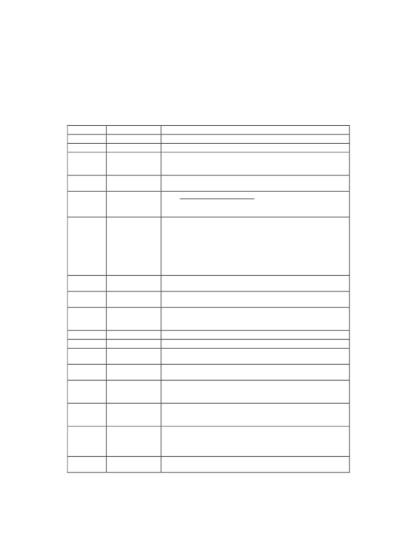
Table 17 – Description of Command Symbols
SYMBOL
C
D
D0, D1
NAME
DESCRIPTION
Cylinder Address The currently selected address; 0 to 255.
Data Pattern
The pattern to be written in each sector data field during formatting.
Drive Select 0-1
Designates which drives are perpendicular drives on the
Perpendicular Mode Command. A "1" indicates a perpendicular
drive.
Direction Control
If this bit is 0, then the head will step out from the spindle during a
relative seek. If set to a 1, the head will step in toward the spindle.
Disk Drive Select DS1 DS0 DRIVE
0 0 Drive 0
0 1 Drive 1
Special Sector
Size
bytes transferred in disk read/write commands. The sector size (N =
0) is set to 128. If the actual sector (on the diskette) is larger than
DTL, the remainder of the actual sector is read but is not passed to
the host during read commands; during write commands, the
remainder of the actual sector is written with all zero bytes. The CRC
check code is calculated with the actual sector. When N is not zero,
DTL has no meaning and should be set to FF HEX.
Enable Count
When this bit is "1" the "DTL" parameter of the Verify command
becomes SC (number of sectors per track).
Enable FIFO
This active low bit when a 0, enables the FIFO. A "1" disables the
FIFO (default).
Enable Implied
Seek
read or write command that requires the C parameter in the
command phase. A "0" disables the implied seek.
End of Track
The final sector number of the current track.
Alters Gap 2 length when using Perpendicular Mode.
Gap Length
The Gap 3 size. (Gap 3 is the space between sectors excluding the
VCO synchronization field).
Head Address
Selected head: 0 or 1 (disk side 0 or 1) as encoded in the sector ID
field.
Head Load Time
The time interval that FDC waits after loading the head and before
initializing a read or write operation. Refer to the Specify command
for actual delays.
Head Unload
Time
write command) until the head is unloaded. Refer to the Specify
command for actual delays.
Lock defines whether EFIFO, FIFOTHR, and PRETRK parameters of
the CONFIGURE COMMAND can be reset to their default values by
a "software Reset". (A reset caused by writing to the appropriate bits
of either the DSR or DOR)
MFM/FM Mode
Selector
density (FM) mode.
DIR
DS0, DS1
DTL
By setting N to zero (00), DTL may be used to control the number of
EC
EFIFO
EIS
When set, a seek operation will be performed before executing any
EOT
GAP
GPL
H/HDS
HLT
HUT
The time interval from the end of the execution phase (of a read or
LOCK
MFM
A one selects the double density (MFM) mode. A zero selects single
相關(guān)PDF資料 |
PDF描述 |
|---|---|
| LPC47M14I-NC | 128 PIN ENGANCED SUPER I/O CONTROLLER WITH AN LPC INTERFACE AND USB HUB |
| LPC47M14K-NC | RESTR 1.50K 1 TOL 1/8W MF |
| LPC47M14P-NC | 128 PIN ENGANCED SUPER I/O CONTROLLER WITH AN LPC INTERFACE AND USB HUB |
| LPC47M14X | 128 PIN ENGANCED SUPER I/O CONTROLLER WITH AN LPC INTERFACE AND USB HUB |
| LPC47M14B-NC | GE KIT:CAT5 VGA VIDEO 4CHSPLITTER & 3 LR REMOTES |
相關(guān)代理商/技術(shù)參數(shù) |
參數(shù)描述 |
|---|---|
| LPC47M14S-NC | 制造商:SMSC 制造商全稱:SMSC 功能描述:128 PIN ENGANCED SUPER I/O CONTROLLER WITH AN LPC INTERFACE AND USB HUB |
| LPC47M14T-NC | 制造商:SMSC 制造商全稱:SMSC 功能描述:128 PIN ENGANCED SUPER I/O CONTROLLER WITH AN LPC INTERFACE AND USB HUB |
| LPC47M14U-NC | 制造商:SMSC 制造商全稱:SMSC 功能描述:128 PIN ENGANCED SUPER I/O CONTROLLER WITH AN LPC INTERFACE AND USB HUB |
| LPC47M14V-NC | 制造商:SMSC 制造商全稱:SMSC 功能描述:128 PIN ENGANCED SUPER I/O CONTROLLER WITH AN LPC INTERFACE AND USB HUB |
| LPC47M14W-NC | 制造商:SMSC 制造商全稱:SMSC 功能描述:128 PIN ENGANCED SUPER I/O CONTROLLER WITH AN LPC INTERFACE AND USB HUB |
發(fā)布緊急采購(gòu),3分鐘左右您將得到回復(fù)。