- 您現(xiàn)在的位置:買賣IC網(wǎng) > PDF目錄385497 > LPC2478FBD208 (NXP Semiconductors N.V.) Single-chip 16-bit-32-bit micro; 512 kB flash, Ethernet, CAN, LCD, USB 2.0 device-host-OTG, external memory interface PDF資料下載
參數(shù)資料
| 型號: | LPC2478FBD208 |
| 廠商: | NXP Semiconductors N.V. |
| 元件分類: | 數(shù)學(xué)處理器 |
| 英文描述: | Single-chip 16-bit-32-bit micro; 512 kB flash, Ethernet, CAN, LCD, USB 2.0 device-host-OTG, external memory interface |
| 封裝: | LPC2478FBD208<SOT459-1 (LQFP208)|<<http://www.nxp.com/packages/SOT459-1.html<1<Always Pb-free,;LPC2478FET208<SOT950-1 (TFBGA208)|<<http://www.nxp.com/packages/SOT950-1.ht |
| 文件頁數(shù): | 19/93頁 |
| 文件大?。?/td> | 751K |
| 代理商: | LPC2478FBD208 |
第1頁第2頁第3頁第4頁第5頁第6頁第7頁第8頁第9頁第10頁第11頁第12頁第13頁第14頁第15頁第16頁第17頁第18頁當(dāng)前第19頁第20頁第21頁第22頁第23頁第24頁第25頁第26頁第27頁第28頁第29頁第30頁第31頁第32頁第33頁第34頁第35頁第36頁第37頁第38頁第39頁第40頁第41頁第42頁第43頁第44頁第45頁第46頁第47頁第48頁第49頁第50頁第51頁第52頁第53頁第54頁第55頁第56頁第57頁第58頁第59頁第60頁第61頁第62頁第63頁第64頁第65頁第66頁第67頁第68頁第69頁第70頁第71頁第72頁第73頁第74頁第75頁第76頁第77頁第78頁第79頁第80頁第81頁第82頁第83頁第84頁第85頁第86頁第87頁第88頁第89頁第90頁第91頁第92頁第93頁
LPC2478
All information provided in this document is subject to legal disclaimers.
NXP B.V. 2011. All rights reserved.
Product data sheet
Rev. 3 — 12 September 2011
19 of 93
NXP Semiconductors
LPC2478
Single-chip 16-bit/32-bit microcontroller
P2[8]/TD2/TXD2/
TRACEPKT3/
LCDVD[2]/
LCDVD[6]
134
[1]
H15
[1]
I/O
O
O
O
O
I/O
O
P2[8] —
General purpose digital input/output pin.
TD2 —
CAN2 transmitter output.
TXD2 —
Transmitter output for UART2.
TRACEPKT3 —
Trace packet, bit 3.
[19]
LCDVD[2]/LCDVD[6] —
LCD data.
[19]
P2[9] —
General purpose digital input/output pin.
USB_CONNECT1 —
USB1 SoftConnect control. Signal used to switch
an external 1.5 k
resistor under the software control. Used with the
SoftConnect USB feature.
RXD2 —
Receiver input for UART2.
EXTIN0 —
External Trigger Input.
[19]
LCDVD[3]/LCDVD[7] —
LCD data.
[19]
P2[10] —
General purpose digital input/output pin.
Note:
LOW on this pin while RESET is LOW forces on-chip bootloader to
take over control of the part after a reset.
EINT0 —
External interrupt 0 input.
P2[11] —
General purpose digital input/output pin.
EINT1 —
External interrupt 1 input.
[20]
LCDCLKIN —
LCD clock.
[20]
MCIDAT1 —
Data line 1 for SD/MMC interface.
I2STX_CLK —
Transmit Clock. It is driven by the master and received by
the slave. Corresponds to the signal SCK in the
I
2
S-bus specification
.
P2[12] —
General purpose digital input/output pin.
EINT2 —
External interrupt 2 input.
[20]
LCDVD[4]/LCDVD[3]/LCDVD[8]/LCDVD[18] —
LCD data.
[20]
MCIDAT2 —
Data line 2 for SD/MMC interface.
I2STX_WS —
Transmit Word Select. It is driven by the master and
received by the slave. Corresponds to the signal WS in the
I
2
S-bus
specification
.
P2[13] —
General purpose digital input/output pin.
EINT3 —
External interrupt 3 input.
[20]
LCDVD[5]/LCDVD[9]/LCDVD[19] —
LCD data.
[20]
MCIDAT3 —
Data line 3 for SD/MMC interface.
I2STX_SDA —
Transmit data. It is driven by the transmitter and read by
the receiver. Corresponds to the signal SD in the
I
2
S-bus specification
.
P2[14] —
General purpose digital input/output pin.
CS2 —
LOW active Chip Select 2 signal.
CAP2[0] —
Capture input for Timer 2, channel 0.
SDA1 —
I
2
C1 data input/output (this is not an open-drain pin).
P2[15] —
General purpose digital input/output pin.
CS3 —
LOW active Chip Select 3 signal.
CAP2[1] —
Capture input for Timer 2, channel 1.
SCL1 —
I
2
C1 clock input/output (this is not an open-drain pin).
P2[9]/
USB_CONNECT1/
RXD2/EXTIN0/
LCDVD[3]/
LCDVD[7]
132
[1]
H16
[1]
I
I
O
I/O
P2[10]/EINT0
110
[6]
N15
[6]
I
I/O
I
O
I/O
I/O
P2[11]/EINT1/
LCDCLKIN/
MCIDAT1/
I2STX_CLK
108
[6]
T17
[6]
P2[12]/EINT2/
LCDVD[4]/
LCDVD[3]/
LCDVD[8]/
LCDVD[18]/
MCIDAT2/
I2STX_WS
106
[6]
N14
[6]
I/O
I
O
I/O
I/O
P2[13]/EINT3/
LCDVD[5]/
LCDVD[9]/
LCDVD[19]/
MCIDAT3/
I2STX_SDA
102
[6]
T16
[6]
I/O
I
O
I/O
I/O
P2[14]/CS2/
CAP2[0]/SDA1
91
[6]
R12
[6]
I/O
O
I
I/O
I/O
O
I
I/O
P2[15]/CS3/
CAP2[1]/SCL1
99
[6]
P13
[6]
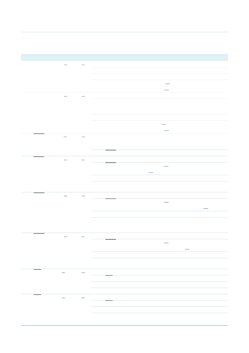
Table 4.
Symbol
Pin description
…continued
Pin
Ball
Type
Description
相關(guān)PDF資料 |
PDF描述 |
|---|---|
| LPC2478FET208 | Single-chip 16-bit-32-bit micro; 512 kB flash, Ethernet, CAN, LCD, USB 2.0 device-host-OTG, external memory interface |
| LPC2917FBD144 | ARM9 microcontroller with CAN and LIN |
| LPC2919FBD144 | ARM9 microcontroller with CAN and LIN |
| LPC2921FBD100 | ARM9 microcontroller with CAN, LIN, and USB |
| LPC2923FBD100 | ARM9 microcontroller with CAN, LIN, and USB |
相關(guān)代理商/技術(shù)參數(shù) |
參數(shù)描述 |
|---|---|
| LPC2478FBD208,551 | 功能描述:ARM微控制器 - MCU LCD CONT/ETHNET USB/512K FL RoHS:否 制造商:STMicroelectronics 核心:ARM Cortex M4F 處理器系列:STM32F373xx 數(shù)據(jù)總線寬度:32 bit 最大時鐘頻率:72 MHz 程序存儲器大小:256 KB 數(shù)據(jù) RAM 大小:32 KB 片上 ADC:Yes 工作電源電壓:1.65 V to 3.6 V, 2 V to 3.6 V, 2.2 V to 3.6 V 工作溫度范圍:- 40 C to + 85 C 封裝 / 箱體:LQFP-48 安裝風(fēng)格:SMD/SMT |
| LPC2478FBD208,551 | 制造商:NXP Semiconductors 功能描述:IC, 32BIT MCU, 72MHZ, LQFP-208 |
| LPC2478FBD208551 | 制造商:NXP Semiconductors 功能描述:MCU ARM7 208LQFP |
| LPC2478FBD208551 | 制造商:NXP Semiconductors 功能描述:IC 32BIT MCU 72MHZ LQFP-208 |
| LPC2478FET,208 | 制造商:NXP Semiconductors 功能描述: |
發(fā)布緊急采購,3分鐘左右您將得到回復(fù)。