- 您現(xiàn)在的位置:買賣IC網(wǎng) > PDF目錄358865 > LM4610 (National Semiconductor Corporation) Dual DC Operated Tone/Volume/Balance Circuit with National 3-D Sound PDF資料下載
參數(shù)資料
| 型號(hào): | LM4610 |
| 廠商: | National Semiconductor Corporation |
| 英文描述: | Dual DC Operated Tone/Volume/Balance Circuit with National 3-D Sound |
| 中文描述: | 雙區(qū)運(yùn)營(yíng)音/音量/平衡電路與全國(guó)3 - D音效 |
| 文件頁(yè)數(shù): | 4/11頁(yè) |
| 文件大小: | 393K |
| 代理商: | LM4610 |
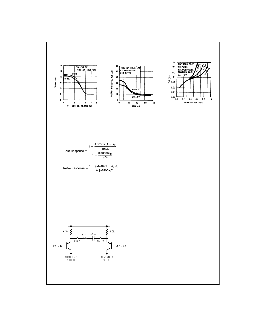
Typical Performance Characteristics
(Continued)
Application Notes
TONE RESPONSE
The maximum boost and cut can be optimized for individual
applications by selection of the appropriate values of C
t
(treble) and C
b
(bass).
The tone responses are defined by the relationships:
Where a
=a
t
=0 for maximum bass and treble boost respec-
tively and a
b
=a
t
=1 for maximum cut.
For the values of C
and C
of 0.39 μF and 0.01 μF as shown
in the Application Circuit, 15 dB of boost or cut is obtained at
40 Hz and 16 kHz.
NATIONAL 3D-SOUND
When stereo speakers need to be closer than optimum be-
cause of equipment /cabinet limitations, an improved stereo
effect can be obtained using a modest amount of phase - re-
versed interchannel cross-coupling. In the LM4610 the input
stage tramsistor emitters are brought out to facillitate this.
The arrangement is shown below in the basic form.
With a monophonic source, the emitters have the same sig-
nal and the resistor and capacitor connected between them
have no effect. With a stereo signal each transistor works in
the grounded base mode for stereo components, generating
an in-phase signal from the opposite channel. As the normal
signals
are
inverted
at
this
phase-reversed cross-coupling is achieved. An effective
level of coupling of 60% can be obtained using 4.7k in con-
junction with the internal 6.5k emitter resistors. At low fre-
quencies, speakers become less directional and it becomes
desirable to reduce the enhancement effect. With a 0.1μF
coupling capacitor, as shown, roll-off occurs below 330 Hz.
The coupling components may be varied for alternative re-
sponses.
point,
the
appropriate
ZENER VOLTAGE
A zener voltage (pin 19=5.4V) is provided which may be
used to bias the control potentiometers. Setting a DC level of
one half of the zener voltage on the control inputs, pins 6,11,
and 16, results in the balanced gain and flat response condi-
tion. Typical spread on the zener voltage is
±
100 mV and
this must be taken into account if control signals are used
which are not referenced to the zener voltage. If this is the
case, then they will need to be derived with similar accuracy.
LOUDNESS COMPENSATION
A simple loudness compensation may be effected by apply-
ing a DC control voltage to pin 9. This operates on the tone
control stages to produce an additional boost limited by the
maximum boost defined by C
and C
. There is no loudness
compensation when pin 9 is connected to pin 19. Pin 9 can
be connected to pin 14 to give the loudness compensated
volume characteristic as illustrated without the addition of
further external components. (Tone settings are for flat re-
sponse, C
and C
as given in Application Circuit.) Modifica-
tion to the loudness characteristic is possible by changing
the capacitors C
and C
for a different basic response or, by
a resistor network between pins 9 and 14 for a different
threshold and slope.
SIGNAL HANDLING
The volume control function of the LM4610 is carried out in
two stages, controlled by the DC voltage on pin 14, to im-
prove signal handling capability and provide a reduction of
output noise level at reduced gain. The first stage is before
the tone control processing and provides an initial 15 dB of
gain reduction, so ensuring that the tone sections are not
overdriven by large input levels when operating with a low
volume setting.Any combination of tone and volume settings
Loudness Control
Characteristic
DS101125-29
Output Noise Voltage
vs Gain
DS101125-30
THD vs Input Voltage
DS101125-31
DS101125-34
www.national.com
4
相關(guān)PDF資料 |
PDF描述 |
|---|---|
| LM4610N | Dual DC Operated Tone/Volume/Balance Circuit with National 3-D Sound |
| LM4664 | Filterless High Efficiency 1.1W Switching Audio Amplifier |
| LM4665 | Filterless High Efficiency 1W Switching Audio Amplifier |
| LM4665ITLX | Filterless High Efficiency 1W Switching Audio Amplifier |
| LM4665LD | Filterless High Efficiency 1W Switching Audio Amplifier |
相關(guān)代理商/技術(shù)參數(shù) |
參數(shù)描述 |
|---|---|
| LM4610N | 制造商:NSC 制造商全稱:National Semiconductor 功能描述:Dual DC Operated Tone/Volume/Balance Circuit with National 3-D Sound |
| LM4651 | 制造商:NSC 制造商全稱:National Semiconductor 功能描述:170W Class D Audio Power Amplifier Solution |
| LM4651_09 | 制造商:NSC 制造商全稱:National Semiconductor 功能描述:170W Class D Audio Power Amplifier Solution |
| LM4651N | 制造商:Texas Instruments 功能描述:IC AUDIO BOOMER CLASS D 170W 4651 |
| LM4651N | 制造商:Texas Instruments 功能描述:IC AUDIO BOOMER CLASS D 170W 4651 |
發(fā)布緊急采購(gòu),3分鐘左右您將得到回復(fù)。