- 您現(xiàn)在的位置:買賣IC網(wǎng) > PDF目錄384598 > LM3370SDX-3621 (NATIONAL SEMICONDUCTOR CORP) Dual Synchronous Step-Down DC-DC Converter with Dynamic Voltage Scaling Function PDF資料下載
參數(shù)資料
| 型號(hào): | LM3370SDX-3621 |
| 廠商: | NATIONAL SEMICONDUCTOR CORP |
| 元件分類: | 穩(wěn)壓器 |
| 英文描述: | Dual Synchronous Step-Down DC-DC Converter with Dynamic Voltage Scaling Function |
| 中文描述: | 1.4 A DUAL SWITCHING CONTROLLER, 2400 kHz SWITCHING FREQ-MAX, PDSO16 |
| 封裝: | 4 X 5 MM, 0.8 MM HEIGHT, LLP-16 |
| 文件頁(yè)數(shù): | 22/26頁(yè) |
| 文件大?。?/td> | 5302K |
| 代理商: | LM3370SDX-3621 |
第1頁(yè)第2頁(yè)第3頁(yè)第4頁(yè)第5頁(yè)第6頁(yè)第7頁(yè)第8頁(yè)第9頁(yè)第10頁(yè)第11頁(yè)第12頁(yè)第13頁(yè)第14頁(yè)第15頁(yè)第16頁(yè)第17頁(yè)第18頁(yè)第19頁(yè)第20頁(yè)第21頁(yè)當(dāng)前第22頁(yè)第23頁(yè)第24頁(yè)第25頁(yè)第26頁(yè)
bias characteristics vary from manufacturer to manufacturer
and dc bias curves should be requested from them as part of
the capacitor selection process.
The output filter capacitor smoothes out current flow from the
inductor to the load, helps maintain a steady output voltage
during transient load changes and reduces output voltage
ripple. These capacitors must be selected with sufficient ca-
pacitance and sufficiently low ESR to perform these functions.
The output ripple voltage can be calculated as:
Voltage peak-to-peak ripple due to capacitance =
Voltage peak-to-peak ripple due to ESR = V
PP-ESR
= I
PP
*R
ESR
Voltage peak-to-peak ripple, root mean squared =
Note that the output ripple is dependent on the current ripple
and the equivalent series resistance of the output capacitor
(R
ESR
). The R
ESR
is frequency dependent (as well as temper-
ature dependent); make sure that the frequency of the R
given is the same order of magnitude as the switching fre-
quency.
TABLE 3. Suggested Capacitors and Their Suppliers
Model
Description
Case
Size
Vendor
4.7 μF for C
IN
C1608X5R0J475
Ceramic, X5R,
6.3V Rating
Ceramic, X5R,
6.3V Rating
Ceramic, X5R,
6.3V Rating
Ceramic, X5R,
6.3V Rating
Ceramic, X5R,
6.3V Rating
0603
TDK
C2012X5R0J475
0805
JMK212BJ475
0805
Taiyo
Yuden
GRM21BR60J475
0805
muRata
GRM219R60J-
475KE19D
0805
(Thin)
<1mm
Height
10μF C
OUT
C2012X5R0J106
Ceramic, X5R,
6.3V Rating
Ceramic, X5R,
6.3V Rating
Ceramic, X5R,
6.3V Rating
Ceramic, X5R,
6.3V Rating
0805
TDK
JMK212BJ106
0805
Taiyo
Yuden
GRM21BR60J106
0805
muRata
GRM219R60J-
106KE19D
0805
(Thin)
< 1mm
Height
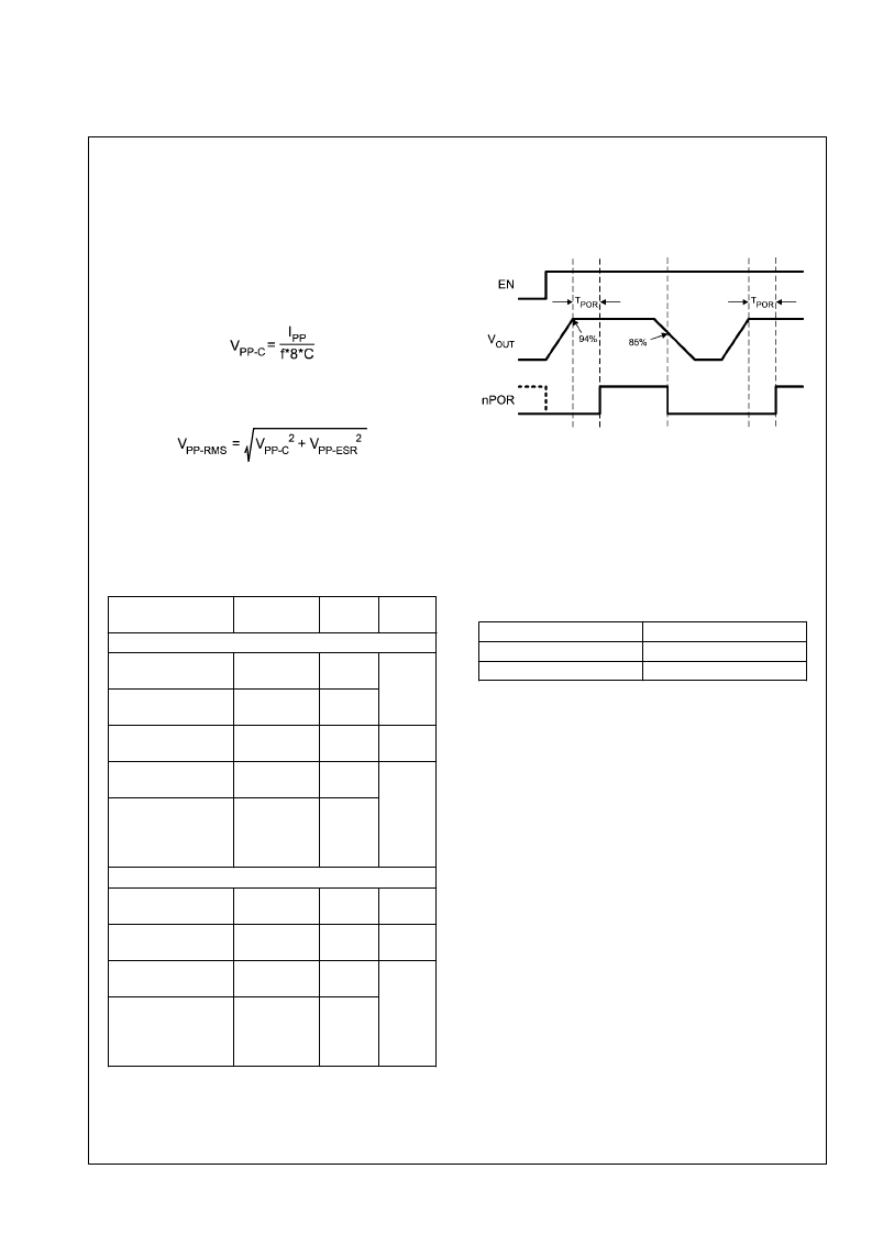
POR (POWER ON RESET)
The LM3370 has an independent POR functions (nPOR) for
each buck converter. The nPOR1 and nPOR2 are open drain
circuits which pull low when the outputs are below 94% (rising
V
) or 85% (falling V
) of the desire output. The inherent
delay between the output (at 94% of V
) to the time at which
the nPOR is enabled is about 50 ms. A pull up resistor of 100
k
at nPOR pin is required. Please refer to the electrical
specification table for other timing options. The diagram be-
low illustrates the timing response of the POR function.
20167319
SPREAD SPECTRUM (SS)
The LM3370 features Spread Spectrum capability, via I
2
C, to
reduce the noise amplitude of the switching frequency during
data transmission. The feature can be enabled by activating
the appropriate control register bit (see register information
section for detail). The main clock of the LM3370 features
spread spectrum at F
= 2 MHz ± 22 kHz ( peak frequency
deviation) with the modulation frequency of either 1 kHz(de-
fault) or 2 kHz via I
2
C. This help reduce noise caused by the
harmonics present in the waveforms at the switch pins of the
buck regulators. It is controlled by I
2
C in the following manner:
I
2
C bit
Modulation Frequency
SS_fmod = 1 (default)
SS_fmod = 0
1 kHz
2 kHz
BOARD LAYOUT CONSIDERATIONS
PC board layout is an important part of DC-DC converter de-
sign. Poor board layout can disrupt the performance of a DC-
DC converter and surrounding circuitry by contributing to EMI,
ground bounce, and resistive voltage loss in the traces. These
can send erroneous signals to the DC-DC converter IC, re-
sulting in poor regulation or instability.
Good layout for the LM3370 can be implemented by following
a few simple design rules:
1.
Place the LM3370, inductor and filter capacitors close
together and make the traces short.
The traces between
these components carry relatively high switching
currents and act as antennas. Following this rule reduces
radiated noise. Place the capacitors and inductor within
0.2 in. (5mm) of the LM3370.
2.
Arrange the components so that the switching current
loops curl in the same direction.
During the first half of
each cycle, current flows from the input filter capacitor,
through the LM3370 and inductor to the output filter
capacitor and back through ground, forming a current
loop. In the second half of each cycle, current is pulled
up from ground, through the LM3370 by the inductor, to
the output filter capacitor and then back through ground,
forming a second current loop. Routing these loops so
the current curls in the same direction prevents magnetic
field reversal between the two half-cycles and reduces
radiated noise.
3.
Connect the ground pins of the LM3370, and filter
capacitors together using generous component-side
www.national.com
22
L
相關(guān)PDF資料 |
PDF描述 |
|---|---|
| LM3370SDX-3806 | Dual Synchronous Step-Down DC-DC Converter with Dynamic Voltage Scaling Function |
| LM3370SDX-4221 | Dual Synchronous Step-Down DC-DC Converter with Dynamic Voltage Scaling Function |
| LM3370TL-3006 | Dual Synchronous Step-Down DC-DC Converter with Dynamic Voltage Scaling Function |
| LM3370TL-3008 | Dual Synchronous Step-Down DC-DC Converter with Dynamic Voltage Scaling Function |
| LM3370TL-3022 | Dual Synchronous Step-Down DC-DC Converter with Dynamic Voltage Scaling Function |
相關(guān)代理商/技術(shù)參數(shù) |
參數(shù)描述 |
|---|---|
| LM3370SDX-3621/NOPB | 功能描述:DC/DC 開(kāi)關(guān)控制器 RoHS:否 制造商:Texas Instruments 輸入電壓:6 V to 100 V 開(kāi)關(guān)頻率: 輸出電壓:1.215 V to 80 V 輸出電流:3.5 A 輸出端數(shù)量:1 最大工作溫度:+ 125 C 安裝風(fēng)格: 封裝 / 箱體:CPAK |
| LM3370SDX-3806 | 制造商:NSC 制造商全稱:National Semiconductor 功能描述:Dual Synchronous Step-Down DC-DC Converter with Dynamic Voltage Scaling Function |
| LM3370SDX-3806/NOPB | 功能描述:DC/DC 開(kāi)關(guān)控制器 RoHS:否 制造商:Texas Instruments 輸入電壓:6 V to 100 V 開(kāi)關(guān)頻率: 輸出電壓:1.215 V to 80 V 輸出電流:3.5 A 輸出端數(shù)量:1 最大工作溫度:+ 125 C 安裝風(fēng)格: 封裝 / 箱體:CPAK |
| LM3370SDX-4221 | 制造商:NSC 制造商全稱:National Semiconductor 功能描述:Dual Synchronous Step-Down DC-DC Converter with Dynamic Voltage Scaling Function |
| LM3370SDX-4221/NOPB | 功能描述:DC/DC 開(kāi)關(guān)控制器 RoHS:否 制造商:Texas Instruments 輸入電壓:6 V to 100 V 開(kāi)關(guān)頻率: 輸出電壓:1.215 V to 80 V 輸出電流:3.5 A 輸出端數(shù)量:1 最大工作溫度:+ 125 C 安裝風(fēng)格: 封裝 / 箱體:CPAK |
發(fā)布緊急采購(gòu),3分鐘左右您將得到回復(fù)。