- 您現(xiàn)在的位置:買賣IC網(wǎng) > PDF目錄358836 > LM2940S-12 (NATIONAL SEMICONDUCTOR CORP) Dual Positive-Edge-Triggered D-Type Flip-Flops With Clear and Preset 14-TVSOP -40 to 85 PDF資料下載
參數(shù)資料
| 型號: | LM2940S-12 |
| 廠商: | NATIONAL SEMICONDUCTOR CORP |
| 元件分類: | 基準(zhǔn)電壓源/電流源 |
| 英文描述: | Dual Positive-Edge-Triggered D-Type Flip-Flops With Clear and Preset 14-TVSOP -40 to 85 |
| 中文描述: | 12 V FIXED POSITIVE LDO REGULATOR, 1 V DROPOUT, PSSO3 |
| 封裝: | TO-263, 3 PIN |
| 文件頁數(shù): | 4/5頁 |
| 文件大小: | 196K |
| 代理商: | LM2940S-12 |
Bay Linear, Inc
2478 Armstrong Street, Livermore, CA 94550 Tel: (925) 989-7144, Fax: (925) 940-9556 www.baylinear.com
LM2940/2941
APPLICATION HINTS
The Bay Linear LM2941 incorporates protection against over-current
faults, reversed load insertion, over temperature operation, and
positive and negative transient voltage. However, the use of an output
capacitor is required in order to insure the stability and the
performances.
Thermal Consideration
Although the LM2941 offers limiting circuitry for overload
conditions, it is necessary not to exceed the maximum junction
temperature, and therefore to be careful about thermal resistance. The
heat flow will follow the lowest resistance path, which is the Junction-
to-case thermal resistance. In order to insure the best thermal flow of
the component, a proper mounting is required. Note that the case of
the device is electrically connected to the output. The
case has to be electrically isolated, a thermally conductive spacer can
be used. However do not forget to consider its contribution to thermal
resistance.
Assuming:
V
IN
= 10V, V
OUT
= 5V, I
OUT
= 1.5A, T
A
= 90
°
C,
θ
CASE
= 1
°
C/W (no
external heat sink, no wind)
Power dissipation under these conditions
P
D
= (V
IN
– V
OUT
) * I
OUT
= 7.5W
Junction Temperature
T
J
= T
A
+ P
D
* (
θ
CASE
+
θ
JC
)
For the Control Section
T
J
= 90
°
C + 7.5W*(1
°
C/W + 0.6
°
C/W) = 102
°
C
114
°
C < T
JUNCTION MAX
for the control section.
For the Power Section
T
J
= 90
°
C + 7.5W*(1
°
C/W + 1.6
°
C/W) = 104.5
°
C
109.5
°
C < T
JUNCTION MAX
for the power transistor.
In both case reliable operation is insured by adequate junction
temperature.
Capacitor Requirements
The output capacitor is needed for stability and to minimize the output
noise. The required value of the capacitor varies with the load.
However, a minimum value of 10
μ
F Aluminum will guarantee
stability over load. A tantalum capacitor is recommended for a fast
load transient response.
If the power source has high AC impedance, a 0.1
μ
F capacitor
between input & ground is recommended. This capacitor should have
good characteristics up to 250 kHz.
Minimum Load Current
To ensure a proper behavior of the regulator at light load, a
minimum load of 5mA for LM2941 is required.
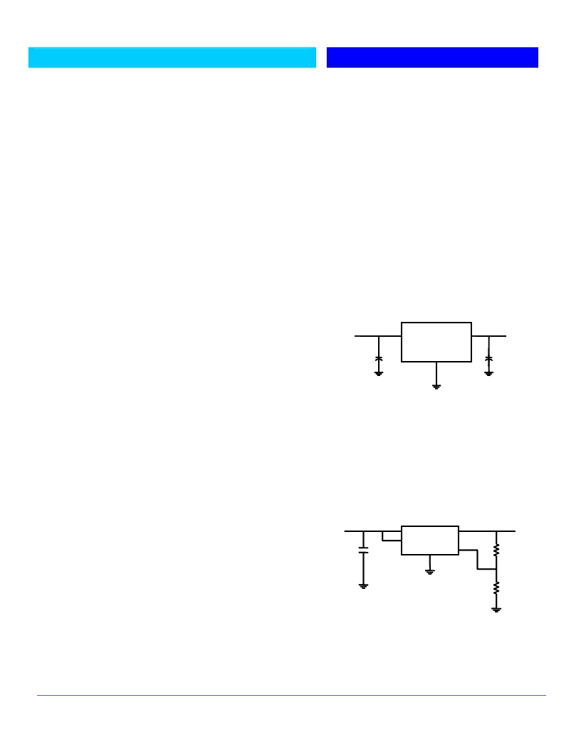
Adjustable Regulator Design
B29152/53 are adjustable regulators and maybe programmed for
any value between 1.25V and 26V using two resistors. The relation
between the resistors is given by:
R
1
=R
2
(V
OUT
/1.240 –1)
Resistors have a large value up to 1m
in order to reduce the
current consumption. This might be interesting in the case of
widely varying load currents.
Enable Input
LM2941 features enable input allowing turning ON & OFF the
device. EN has been designed to be compatible with TTL/CMOS
logic. When the regulator is ON, the current flowing through this
pin is approximately 20
μ
A.
4
5
3
2
1
B2941
V
OUT
V
IN
R
1
R
2
Fig. 2 Adjustable Output Voltage Regulator
2
)]
For best results, the total series resistance should be small
enough to pass the minimum regulator load current
BAY
V
OUT
= V
REF
X [1 + (R
1
/
B2940
Fig.1 Basic Fixed Output Regulator
V
OU
T
V
IN
BAY
相關(guān)PDF資料 |
PDF描述 |
|---|---|
| LM2940S-5.0 | Dual Positive-Edge-Triggered D-Type Flip-Flops With Clear and Preset 14-TVSOP -40 to 85 |
| LM2940S-8.0 | Dual Positive-Edge-Triggered D-Type Flip-Flops With Clear and Preset 14-SOIC -40 to 85 |
| LM2940T-12 | Dual Positive-Edge-Triggered D-Type Flip-Flops With Clear and Preset 14-PDIP -40 to 85 |
| LM2940T-5.0 | Dual Positive-Edge-Triggered D-Type Flip-Flops With Clear and Preset 14-PDIP -40 to 85 |
| LM2940CS-12 | Cap-Free, NMOS, 150mA Low Dropout Regulator with Reverse Current Protection |
相關(guān)代理商/技術(shù)參數(shù) |
參數(shù)描述 |
|---|---|
| LM2940S-12/NOPB | 功能描述:低壓差穩(wěn)壓器 - LDO 1A LDO REG RoHS:否 制造商:Texas Instruments 最大輸入電壓:36 V 輸出電壓:1.4 V to 20.5 V 回動電壓(最大值):307 mV 輸出電流:1 A 負(fù)載調(diào)節(jié):0.3 % 輸出端數(shù)量: 輸出類型:Fixed 最大工作溫度:+ 125 C 安裝風(fēng)格:SMD/SMT 封裝 / 箱體:VQFN-20 |
| LM2940S-12/NOPB | 制造商:Texas Instruments 功能描述:Linear Voltage Regulator IC |
| LM2940S-5.0 | 功能描述:低壓差穩(wěn)壓器 - LDO RoHS:否 制造商:Texas Instruments 最大輸入電壓:36 V 輸出電壓:1.4 V to 20.5 V 回動電壓(最大值):307 mV 輸出電流:1 A 負(fù)載調(diào)節(jié):0.3 % 輸出端數(shù)量: 輸出類型:Fixed 最大工作溫度:+ 125 C 安裝風(fēng)格:SMD/SMT 封裝 / 箱體:VQFN-20 |
| LM2940S-5.0 | 制造商:Texas Instruments 功能描述:V REG LDO +5.0V SMD 2940 TO2633 |
| LM2940S-5.0/HALF | 制造商:Texas Instruments 功能描述:V REG LDO +5.0V SMD 2940 TO2633 |
發(fā)布緊急采購,3分鐘左右您將得到回復(fù)。