- 您現(xiàn)在的位置:買賣IC網(wǎng) > PDF目錄358819 > LM2574-3.3BWM (MICREL INC) 52kHz Simple 0.5A Buck Regulator PDF資料下載
參數(shù)資料
| 型號(hào): | LM2574-3.3BWM |
| 廠商: | MICREL INC |
| 元件分類: | 穩(wěn)壓器 |
| 英文描述: | 52kHz Simple 0.5A Buck Regulator |
| 中文描述: | 1.8 A SWITCHING REGULATOR, 63 kHz SWITCHING FREQ-MAX, PDSO14 |
| 封裝: | SOIC-14 |
| 文件頁數(shù): | 10/24頁 |
| 文件大小: | 397K |
| 代理商: | LM2574-3.3BWM |
LM2574
10
MOTOROLA ANALOG IC DEVICE DATA
Procedure (Fixed Output Voltage Version)
In order to simplify the switching regulator design, a step–by–step
design procedure and example is provided.
Procedure
Example
Given Parameters:
Vout = Regulated Output Voltage (3.3 V, 5.0 V, 12 V or 15 V)
Vin(max) = Maximum Input Voltage
ILoad(max) = Maximum Load Current
Given Parameters:
Vout = 5.0 V
Vin(max) = 15 V
ILoad(max) = 0.4 A
1. Controller IC Selection
According to the required input voltage, output voltage and
current, select the appropriate type of the controller IC output
voltage version.
1. Controller IC Selection
According to the required input voltage, output voltage, current
polarity and current value, use the LM2574–5 controller IC.
2. Input Capacitor Selection (Cin)
To prevent large voltage transients from appearing at the input
and for stable operation of the converter, an aluminium or
tantalum electrolytic bypass capacitor is needed between the
input pin +Vin and ground pin Gnd. This capacitor should be
located close to the IC using short leads. This capacitor should
have a low ESR (Equivalent Series Resistance) value.
2. Input Capacitor Selection (Cin)
A 22
μ
F, 25 V aluminium electrolytic capacitor located near to
the input and ground pins provides sufficient bypassing.
3. Catch Diode Selection (D1)
A.
Since the diode maximum peak current exceeds the
regulator maximum load current, the catch diode current
rating must be at least 1.2 times greater than the maximum
load current. For a robust design the diode should have a
current rating equal to the maximum current limit of the
LM2574 to be able to withstand a continuous output short.
B.
The reverse voltage rating of the diode should be at least
1.25 times the maximum input voltage.
3. Catch Diode Selection (D1)
A
.For this example the current rating of the diode is 1.0 A.
B.
Use a 20 V 1N5817 Schottky diode, or any of the
suggested fast recovery diodes shown in Table 1.
4. Inductor Selection (L1)
A.
According to the required working conditions, select the
correct inductor value using the selection guide from
Figures 19 to 23.
B.
From the appropriate inductor selection guide, identify the
inductance region intersected by the Maximum Input Voltage
line and the Maximum Load Current line. Each region is
identified by an inductance value and an inductor code.
C.
Select an appropriate inductor from the several different
manufacturers part numbers listed in Table 2. The designer
must realize that the inductor current rating must be higher
than the maximum peak current flowing through the inductor.
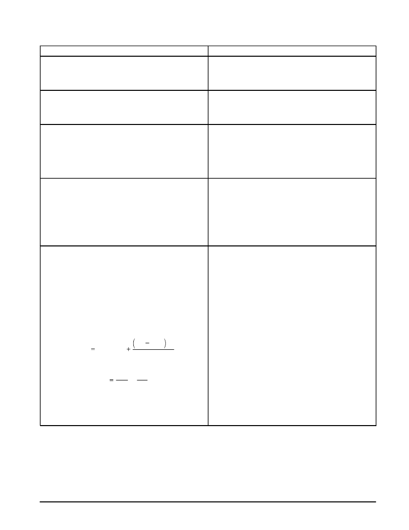
This maximum peak current can be calculated as follows:
where ton is the “on” time of the power switch and
V
out
V
in
For additional information about the inductor, see the inductor
section in the “EXTERNAL COMPONENTS” section of this
data sheet.
I
p
(
max
)
I
Load
(
max
)
V
in
V
out
t
on
2L
t
on
xf
osc
4. Inductor Selection (L1)
A.
Use the inductor selection guide shown in Figure 20.
B.
From the selection guide, the inductance area intersected
by the 15 V line and 0.4 A line is 330.
C.
Inductor value required is 330
μ
H. From Table 2, choose an
inductor from any of the listed manufacturers.
相關(guān)PDF資料 |
PDF描述 |
|---|---|
| LM2574-12BWM | 52kHz Simple 0.5A Buck Regulator |
| LM2574BWM | SWITCH PB SPST-NO MOM 3A RED |
| LM2574-3.3BN | 52KHZ SIMPLE 0.5A BUCK REGULATOR |
| LM2574-12BN | 52kHz Simple 0.5A Buck Regulator |
| LM2574 | SIMPLE SWITCHER⑩ 0.5A Step-Down Voltage Regulator |
相關(guān)代理商/技術(shù)參數(shù) |
參數(shù)描述 |
|---|---|
| LM2574-5 | 制造商:MOTOROLA 制造商全稱:Motorola, Inc 功能描述:EASY SWITCHERE⑩ 0.5 A STEP-DOWN VOLTAGE REGULATOR |
| LM2574-5.0 WAF | 制造商:Texas Instruments 功能描述: |
| LM2574-5.0BN | 功能描述:IC REG BUCK 5V 0.5A 8DIP RoHS:否 類別:集成電路 (IC) >> PMIC - 穩(wěn)壓器 - DC DC 開關(guān)穩(wěn)壓器 系列:- 標(biāo)準(zhǔn)包裝:20 系列:SIMPLE SWITCHER® 類型:降壓(降壓) 輸出類型:固定 輸出數(shù):1 輸出電壓:12V 輸入電壓:4 V ~ 60 V PWM 型:電壓模式 頻率 - 開關(guān):52kHz 電流 - 輸出:1A 同步整流器:無 工作溫度:-40°C ~ 125°C 安裝類型:通孔 封裝/外殼:16-DIP(0.300",7.62mm) 包裝:管件 供應(yīng)商設(shè)備封裝:16-DIP 其它名稱:*LM2575HVN-12LM2575HVN-12 |
| LM2574-5.0BWM | 制造商:Rochester Electronics LLC 功能描述:- Bulk |
| LM2574-5.0YN | 功能描述:直流/直流開關(guān)調(diào)節(jié)器 0.5A Step-Down SMPS Regulator (Lead Free) RoHS:否 制造商:International Rectifier 最大輸入電壓:21 V 開關(guān)頻率:1.5 MHz 輸出電壓:0.5 V to 0.86 V 輸出電流:4 A 輸出端數(shù)量: 最大工作溫度: 安裝風(fēng)格:SMD/SMT 封裝 / 箱體:PQFN 4 x 5 |
發(fā)布緊急采購,3分鐘左右您將得到回復(fù)。