- 您現(xiàn)在的位置:買賣IC網(wǎng) > PDF目錄358813 > LM1800N (NATIONAL SEMICONDUCTOR CORP) LM1800 Phase-Locked Loop FM Stereo Demodulator PDF資料下載
參數(shù)資料
| 型號: | LM1800N |
| 廠商: | NATIONAL SEMICONDUCTOR CORP |
| 元件分類: | 消費家電 |
| 英文描述: | LM1800 Phase-Locked Loop FM Stereo Demodulator |
| 中文描述: | SPECIALTY CONSUMER CIRCUIT, PDIP16 |
| 封裝: | PLASTIC, DIP-16 |
| 文件頁數(shù): | 2/4頁 |
| 文件大?。?/td> | 108K |
| 代理商: | LM1800N |
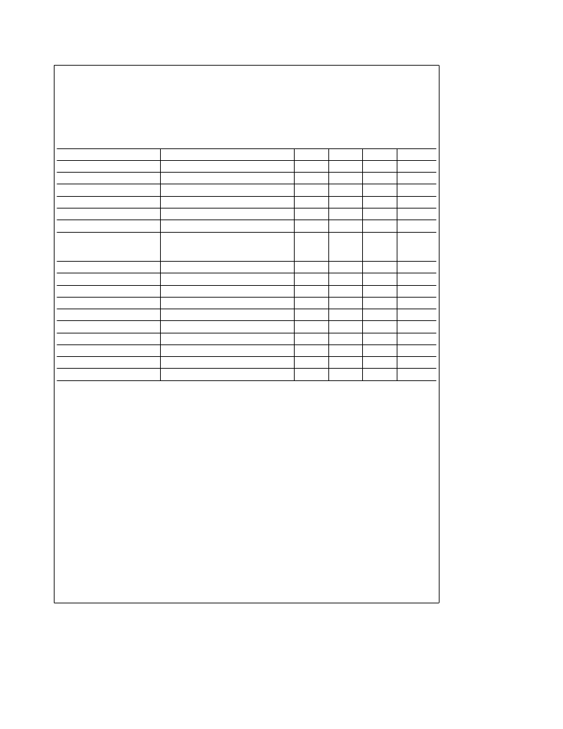
Absolute Maximum Ratings
If Military/Aerospace specified devices are required,
please contact the National Semiconductor Sales
Office/Distributors for availability and specifications.
Supply Voltage
18V
Power Dissipation (Note 3)
1500 mW
Operating Temperature Range
0
§
C to
a
70
§
C
a
10V to
a
18V
b
65
§
C to
a
150
§
C
Operating Supply Voltage Range
Storage Temperature Range
Lead Temperature (Soldering, 10 sec)
260
§
C
Electrical Characteristics
(Note 1)
Parameter
Conditions
Min
Typ
Max
Units
Supply Current
Lamp ‘‘Off’’
21
30
mA
Lamp Driver Saturation
100 mA Lamp Current
1.3
1.8
V
Lamp Driver Leakage
1.0
nA
Pilot Level for Lamp ‘‘ON’’
Pin 11 Adjusted to 19.00 kHz
15
20
mVrms
Pilot Level for Lamp ‘‘OFF’’
Pin 11 Adjusted to 19.00 kHz
3.0
7.0
mVrms
Stereo Lamp Hysteresis
3.0
6.0
dB
Stereo Channel Separation
100 Hz (Note 2)
1000 Hz (Note 2)
10000 Hz (Note 2)
40
45
45
dB
dB
dB
30
Monaural Channel Unbalance
200 mVrms, 1000 Hz Input
0.3
1.5
dB
Monaural Voltage Gain
200 mVrms, 400 Hz Input
140
200
260
mVrms
Total Harmonic Distortion
500 mVrms, 1000 Hz Input
0.4
1.0
%
Total Harmonic Distortion
500 mVrms, 1000 Hz Input, 1800A Only
0.1
0.3
%
Capture Range
25 mVrms of Pilot
g
2.0
g
6.0
% of f
o
Supply Ripple Rejection
200 mVrms of 200 Hz Ripple
35
45
dB
Dynamic Input Resistance
20
45
k
X
Dynamic Output Resistance
900
1300
2000
X
SCA Rejection
(Note 4)
70
dB
Ultrasonic Freq. Rejection
Combined 19 and 38 kHz, Ref. to Output
33
dB
Note 1:
T
A
e
25
§
C and V
a
e
12V unless otherwise stated.
Note 2:
The stereo input signal is made by summing 123 mVrms LEFT or RIGHT modulated signal with 25 mVrms of 19 kHz pilot tone, measuring all voltages with
an average responding meter calibrated in rms. The resulting waveform is about 800 mVp-p.
Note 3:
For operation in ambient temperatures above 25
§
C, the device must be derated based on a 150
§
C maximum junction temperature and a thermal resistance
of 80
§
C/W junction to ambient.
Note 4:
Measured with a stereo composite signal consistency of 80% stereo, 10% pilot and 10% SCA as defined in the FCC Rules on Broadcasting.
Note 5:
VCO ‘‘OFF’’ curve represents the distortion attainable using good 19 kHz and 38 kHz filters.
2
相關PDF資料 |
PDF描述 |
|---|---|
| LM1801 | BATTERY OPERATED POWER COMPARATOR |
| LM1801N | BATTERY OPERATED POWER COMPARATOR |
| LM180Z | GREEN OVAL LAMP LED |
| LM181E1 | 18 SXGA TFT LCD |
| LM1812N | SONAR CIRCUIT|BIPOLAR|DIP|18PIN|PLASTIC |
相關代理商/技術參數(shù) |
參數(shù)描述 |
|---|---|
| LM1800N/B+ | 制造商:未知廠家 制造商全稱:未知廠家 功能描述:FM Receiver Circuit |
| LM1801 | 制造商:NSC 制造商全稱:National Semiconductor 功能描述:BATTERY OPERATED POWER COMPARATOR |
| LM1801N | 制造商:NSC 制造商全稱:National Semiconductor 功能描述:BATTERY OPERATED POWER COMPARATOR |
| LM1801N/B+ | 制造商:未知廠家 制造商全稱:未知廠家 功能描述:Analog Comparator |
| LM1804 | 制造商:NSC 制造商全稱:National Semiconductor 功能描述:5A型低壓差穩(wěn)壓器陽性 |
發(fā)布緊急采購,3分鐘左右您將得到回復。