- 您現(xiàn)在的位置:買賣IC網(wǎng) > PDF目錄358806 > LM117-220M-B Voltage Regulator PDF資料下載
參數(shù)資料
| 型號: | LM117-220M-B |
| 英文描述: | Voltage Regulator |
| 中文描述: | 電壓調節(jié)器 |
| 文件頁數(shù): | 6/15頁 |
| 文件大小: | 469K |
| 代理商: | LM117-220M-B |
Application Hints
(Continued)
or less and 10 μF capacitance. Figure 3 shows an LM117HV
with protection diodes included for use with outputs greater
than 25V and high values of output capacitance.
Current Limit
Internal current limit will be activated whenever the output
current exceeds the limit indicated in the Typical Perfor-
mance Characteristics. However, if during a short circuit con-
dition the regulator’s differential voltage exceeds the Abso-
lute Maximum Rating of 60V (e.g. V
≥
60V, V
= 0V),
internal junctions in the regulator may break down and the
device may be damaged or fail. Failure modes range from an
apparent open or short from input to output of the regulator,
to a destroyed package (most common with the TO-220
package). To protect the regulator, the user is advised to be
aware of voltages that may be applied to the regulator during
fault conditions, and to avoid violating the Absolute Maxi-
mum Ratings.
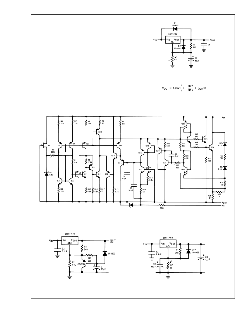
Note:
D1 protects against C1
D2 protects against C2
Schematic Diagram
Typical Applications
DS009062-7
FIGURE 3. Regulator with Protection Diodes
DS009062-8
Slow Turn-On 15V Regulator
DS009062-9
Adjustable Regulator with Improved
Ripple Rejection
DS009062-10
Solid tantalum
*Discharges C1 if output is shorted to ground
L
www.national.com
6
相關PDF資料 |
PDF描述 |
|---|---|
| LM117-220M-ISO | Voltage Regulator |
| LM117AHV-220M | Voltage Regulator |
| LM117AHV-220M-ISO | Voltage Regulator |
| LM117D2T | Analog IC |
| LM117E | Positive Adjustable Voltage Regulator |
相關代理商/技術參數(shù) |
參數(shù)描述 |
|---|---|
| LM117-220M-ISO | 制造商:未知廠家 制造商全稱:未知廠家 功能描述:Voltage Regulator |
| LM1177K | 制造商:n/a 功能描述:1177 (STEEL) |
| LM117883 | 制造商:n/a 功能描述:117/883 SEE NOTES |
| LM117A | 制造商:SEME-LAB 制造商全稱:Seme LAB 功能描述:1.5 AMP POSITIVE ADJUSTABLE VOLTAGE REGULATOR FOR HI-REL APPLICATIONS |
| LM117AG | 制造商:未知廠家 制造商全稱:未知廠家 功能描述:Voltage Regulator |
發(fā)布緊急采購,3分鐘左右您將得到回復。