- 您現(xiàn)在的位置:買賣IC網(wǎng) > PDF目錄44018 > LK1601-9RD8B1 1-OUTPUT 150 W AC-DC REG PWR SUPPLY MODULE PDF資料下載
參數(shù)資料
| 型號: | LK1601-9RD8B1 |
| 元件分類: | 電源模塊 |
| 英文描述: | 1-OUTPUT 150 W AC-DC REG PWR SUPPLY MODULE |
| 封裝: | METAL, CASE K02, MODULE |
| 文件頁數(shù): | 11/27頁 |
| 文件大小: | 640K |
| 代理商: | LK1601-9RD8B1 |
第1頁第2頁第3頁第4頁第5頁第6頁第7頁第8頁第9頁第10頁當(dāng)前第11頁第12頁第13頁第14頁第15頁第16頁第17頁第18頁第19頁第20頁第21頁第22頁第23頁第24頁第25頁第26頁第27頁
K-Family
DC-DC Converters >100 W
Rugged Environment
8 - 20
Edition 2/96 - Melcher AG
MELCHER
The Power Partners.
8.1
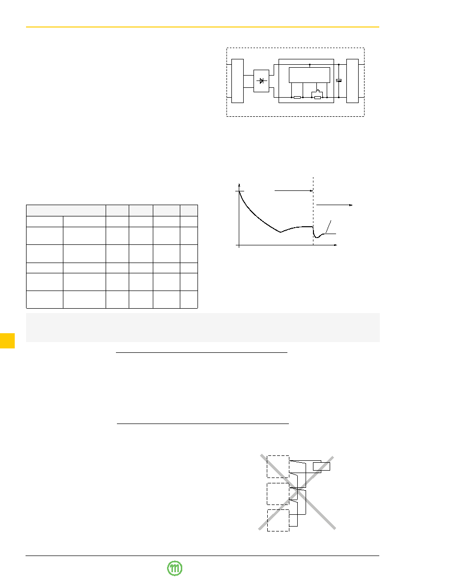
Option E Inrush Current Limitation
CK/DK/EK/LK types may be supplemented by an elec-
tronic circuit (option E, replacing the standard built-in NTC)
to achieve an enhanced inrush current limiting function (not
available with AK/BK/FK types).
If fitted with option E (inrush current limitation) together with
option D6, input voltage monitoring, the CK units meet the
CEPT/ETSI standards for 48 V DC supply voltages accord-
ing to prETS 300132-2, version 4.2, date 9312. Option D6,
externally adjustable via potentiometer, is necessary to dis-
able the converter at input voltages below actual service
voltage ranges, avoiding an excessive input current when
the
input
voltage
is
raised
slowly
according
to
prETS 300132-2. Option D6 threshold level should be ad-
justed to 36.0...40.5 V for 48 V nominal supply systems or
44.0...50.0 V for 60 V nominal supply systems (refer also to
description of option D). The D output should be connected
to the inhibit input. Please contact Melcher if applications
do not permit potentiometer setting.
RV: Current limiting resistance = RS + RI = 15
[A]
Ui/RV
<30
t [ms]
Capacitor
Ci
fully charged
Normal operation
(current limiting
circuit is fully
conducting)
0
Ii = Pi/Ui
Fig. 20
Inrush current with option E
Vo+
Vo–
Vo+
Vo–
Load
Vo+
Vo–
Table 14: Inrush current characteristics with option E
Characteristics
CK
DK
EK/LK
Unit
Ui nom, Io nom Input voltage
60
110
220
V
Iinr p
Peak inrush
6.8
7.4
14.6
A
current
tinr
Inrush current
18
14
16
ms
duration
Ui max, Io nom Input voltage
140
220
380
V
Iinr p
Peak inrush
9.3
14.5
25.3
A
current
tinr
Inrush current
20
14
12
ms
duration
Precaution:
Subsequent switch-on cycles at start-up are limited to max. 10 cycles during the first 20 seconds (cold unit) and at con-
tinuing on/off (
TC =95°C) max. 1 cycle every 8 sec.
Input
Filter
Control
Converter
FET
Ci
RI
RS
Rectifier
(LK types)
Fig. 19
Option E block diagram
Fig. 21
An example of poor wiring for connection in parallel
Option T Current Sharing
This option ensures that the output currents are approxi-
mately shared between all paralleled modules and in-
creases system reliability. To use this facility, simply inter-
connect the T pins of all modules and make sure, that pins
no. 14, the S– pins (K 1000) or the Vo1– pins (K 2000) are
also connected together. The load leads should have equal
length and cross section to ensure equal voltage drops. Not
more than 5 units should be connected in parallel. If output
voltage adjustment is requested we strongly recommend to
use the R-input instead of option P, as with option P the re-
quired setting accuracy is difficult to achieve. The output
voltages must be individually set prior to paralleling to
within a tolerance of 1...2% or the R pins should be con-
nected together.
Option P Potentiometer
The potentiometer provides an output voltage adjustment
range of +10/–60 % of
Uo nom and is accessible through a
hole in the front cover. This feature enables compensation
for voltage drops across the connector and wiring. Option P
is not recommended if units are connected in parallel.
Option P excludes the R-function. With double output units
both outputs are affected by the potentiometer setting (dou-
bling the voltage setting if the outputs are in series).
If the output voltages are increased above
Uo nom via R-in-
put control, option P setting, remote sensing or option T, the
output current(s) should be reduced accordingly so that
Po nom is not exceeded.
相關(guān)PDF資料 |
PDF描述 |
|---|---|
| LK2320-7ERD8B1 | 2-OUTPUT 150 W AC-DC REG PWR SUPPLY MODULE |
| LK2320-7RD0B1 | 2-OUTPUT 150 W AC-DC REG PWR SUPPLY MODULE |
| LK2320-7RD3T | 2-OUTPUT 150 W AC-DC REG PWR SUPPLY MODULE |
| LK2320-9ERD8B1 | 2-OUTPUT 150 W AC-DC REG PWR SUPPLY MODULE |
| LK2320-9PD5TB1 | 2-OUTPUT 150 W AC-DC REG PWR SUPPLY MODULE |
相關(guān)代理商/技術(shù)參數(shù) |
參數(shù)描述 |
|---|---|
| LK1608100K-T | 功能描述:固定電感器 INDCTR STD MULTILYR 0603 10uH 10% RoHS:否 制造商:AVX 電感:10 uH 容差:20 % 最大直流電流:1 A 最大直流電阻:0.075 Ohms 工作溫度范圍:- 40 C to + 85 C 自諧振頻率:38 MHz Q 最小值:40 尺寸:4.45 mm W x 6.6 mm L x 2.92 mm H 屏蔽:Shielded 端接類型:SMD/SMT 封裝 / 箱體:6.6 mm x 4.45 mm |
| LK1608100K-T | 制造商:TAIYO YUDEN 功能描述:Inductor Series:LF LK 制造商:TAIYO YUDEN 功能描述:MULTI-LAYER SMD INDUCTOR |
| LK-1608-100KTK | 功能描述:固定電感器 10uH 5mA 10% Wound Chip RoHS:否 制造商:AVX 電感:10 uH 容差:20 % 最大直流電流:1 A 最大直流電阻:0.075 Ohms 工作溫度范圍:- 40 C to + 85 C 自諧振頻率:38 MHz Q 最小值:40 尺寸:4.45 mm W x 6.6 mm L x 2.92 mm H 屏蔽:Shielded 端接類型:SMD/SMT 封裝 / 箱體:6.6 mm x 4.45 mm |
| LK1608100M-T | 功能描述:固定電感器 INDCTR STD MULTILYR 0603 10uH 20% RoHS:否 制造商:AVX 電感:10 uH 容差:20 % 最大直流電流:1 A 最大直流電阻:0.075 Ohms 工作溫度范圍:- 40 C to + 85 C 自諧振頻率:38 MHz Q 最小值:40 尺寸:4.45 mm W x 6.6 mm L x 2.92 mm H 屏蔽:Shielded 端接類型:SMD/SMT 封裝 / 箱體:6.6 mm x 4.45 mm |
| LK1608120K-T | 功能描述:固定電感器 INDCTR STD MULTILYR 0603 12uH 10% RoHS:否 制造商:AVX 電感:10 uH 容差:20 % 最大直流電流:1 A 最大直流電阻:0.075 Ohms 工作溫度范圍:- 40 C to + 85 C 自諧振頻率:38 MHz Q 最小值:40 尺寸:4.45 mm W x 6.6 mm L x 2.92 mm H 屏蔽:Shielded 端接類型:SMD/SMT 封裝 / 箱體:6.6 mm x 4.45 mm |
發(fā)布緊急采購,3分鐘左右您將得到回復(fù)。