- 您現(xiàn)在的位置:買賣IC網(wǎng) > PDF目錄377642 > LH1550AT1 (VISHAY SEMICONDUCTORS) LH1550AAB1, LH1550AAB1TR, LH1550AT1 1 Form A High-Voltage Solid-State Relay PDF資料下載
參數(shù)資料
| 型號: | LH1550AT1 |
| 廠商: | VISHAY SEMICONDUCTORS |
| 元件分類: | 特殊繼電器 |
| 英文描述: | LH1550AAB1, LH1550AAB1TR, LH1550AT1 1 Form A High-Voltage Solid-State Relay |
| 中文描述: | Solid State Relays Normally Open Form 1A 350V |
| 文件頁數(shù): | 1/6頁 |
| 文件大?。?/td> | 136K |
| 代理商: | LH1550AT1 |
LH1550AAB1, LH1550AAB1TR, LH1550AT1
www.vishay.com
Vishay Semiconductors
Rev. 1.9, 25-Jul-11
1
Document Number: 83841
For technical questions, contact:
optocoupleranswers@vishay.com
THIS DOCUMENT IS SUBJECT TO CHANGE WITHOUT NOTICE. THE PRODUCTS DESCRIBED HEREIN AND THIS DOCUMENT
ARE SUBJECT TO SPECIFIC DISCLAIMERS, SET FORTH AT
www.vishay.com/doc91000
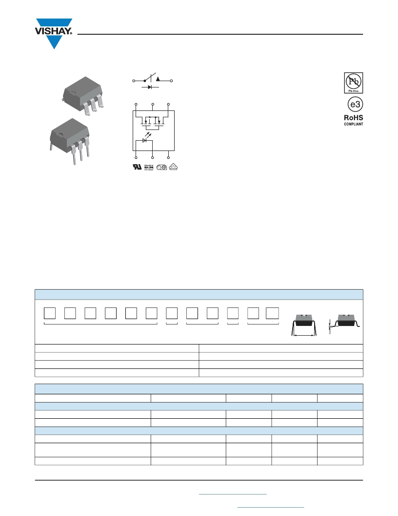
1 Form A High-Voltage Solid-State Relay
DESCRIPTION
The LH1550 is robust, ideal for telecom and ground fault
applications. It is an SPST normally open switch (1 form A)
that replaces electromechanical relays in many applications.
It is similar to the LH1540, but has a characteristically higher
On resistance. It is constructed using a GaAIAs LED for
actuation control and an integrated monolithic die for the
switch output. The die, fabricated in a high-voltage
dielectrically isolated technology, is comprised of a
photodiode array, switch control circuitry and MOSFET
switches. In addition, it employs current-limiting circuitry
which meets lightning surge testing as per ANSI/TIA-968-B
and other regulatory voltage surge requirements when
overvoltage protection is provided.
FEATURES
Current limit protection
Isolation test voltage 5300 V
RMS
Typical R
ON
28
Load voltage 350 V
Load current 120 mA
High surge capability
Clean bounce free switching
Low power consumption
SMD lead available on tape and reel
Compliant to RoHS Directive 2002/95/EC and in
accordance to WEEE 2002/96/EC
APPLICATIONS
General telecom switching
Instrumentation
Industrial controls
6
S
'
S
NC
1
5
2
4
3
S
S
'
i179041-2
DIP
S
MD
AGENCY APPROVALS
UL1577: file no. E52744 system code H, double protection
BSI:
7979/7980
DIN EN:
60747-5-2 (VDE 0884)/60747-5-5 (pending),
available with option 1
FIMKO:
25419
ORDERING INFORMATION
L
H
1
5
5
0
#
#
#
1
T
R
PART NUMBER
ELECTR.
VARIATION
PACKAGE
CONFIG.
NO DC
CONTACT
AT PIN 5
TAPE AND
REEL
PACKAGE
SMD-6
SMD-6, tape and reel
DIP-6, thru hole
UL, BSI, FIMKO
LH1550AAB1
LH1550AAB1TR
LH1550AT1
ABSOLUTE MAXIMUM RATINGS
(T
amb
= 25 °C, unless otherwise specified)
PARAMETER
INPUT
LED continuous forward current
LED reverse voltage
OUTPUT
DC or peak AC load voltage
Continuous DC load current -
bidirectional operation
Peak load current (single shot)
TEST CONDITION
SYMBOL
VALUE
UNIT
I
F
V
R
50
8
mA
V
I
R
10 μA
I
L
50 μA
V
L
350
V
I
L
100
mA
t = 100 ms
I
P
(1)
> 0.1 mm
7.62 mm
DIP
S
MD
相關PDF資料 |
PDF描述 |
|---|---|
| LH1556AB | RLY SSR 50MA 1.45V DC-IN 0.25A 350V AC/DC-OUT 8PDIP - Bulk |
| LH1556FP | Relay SSR 50mA 1.45V DC-IN 0.12A 350V AC/DC-OUT 8-Pin SMD Tube |
| LH1556AACTR | Relay SSR 50mA 1.45V DC-IN 0.12A 350V AC/DC-OUT 8-Pin PDIP SMD T/R |
| LH1556AAC | Relay SSR 50mA 1.45V DC-IN 0.12A 350V AC/DC-OUT 8-Pin PDIP SMD Tube |
| LH2101A | Single General Purpose Single Operational Amplifier(單通道通用運算放大器) |
相關代理商/技術參數(shù) |
參數(shù)描述 |
|---|---|
| LH1554M | 制造商:未知廠家 制造商全稱:未知廠家 功能描述:LCD Display Driver |
| LH1554P | 制造商:未知廠家 制造商全稱:未知廠家 功能描述:LCD Display Driver |
| LH15550 | 制造商:TE Connectivity 功能描述: |
| LH1556AAC | 功能描述:固態(tài)繼電器-PCB安裝 Dual Normally Open Form 1A 350V RoHS:否 制造商:Omron Electronics 控制電壓范圍: 負載電壓額定值:40 V 負載電流額定值:120 mA 觸點形式:1 Form A (SPST-NO) 輸出設備:MOSFET 封裝 / 箱體:USOP-4 安裝風格:SMD/SMT |
| LH1556AAC_11 | 制造商:VISHAY 制造商全稱:Vishay Siliconix 功能描述:Dual 1 Form A Solid-State Relay |
發(fā)布緊急采購,3分鐘左右您將得到回復。