- 您現(xiàn)在的位置:買賣IC網(wǎng) > PDF目錄358775 > LD3521PGK-011 (PerkinElmer Inc.) Low-Cost Digital Linescan Camera PDF資料下載
參數(shù)資料
| 型號(hào): | LD3521PGK-011 |
| 廠商: | PerkinElmer Inc. |
| 英文描述: | Low-Cost Digital Linescan Camera |
| 中文描述: | 低成本數(shù)字線掃描相機(jī) |
| 文件頁(yè)數(shù): | 3/8頁(yè) |
| 文件大小: | 179K |
| 代理商: | LD3521PGK-011 |
Digital Linescan C amera
www.perkinelmer.com/opto
Input/Output Signal Specifications
(Continued)
Enable (LEN).
The Camera Clock (CCLK) operates at
either the MCLK frequency or default
camera frequency, and is synchronized to
the analog video. The output of the CCLK
signal can be used to capture digital video
data by a frame grabber or digitizer.
The Line Enable (LEN) signal brackets the
valid digital video. The signal becomes
high one CCLK period before the first valid
pixel and goes low one CCLK period before
the last valid pixel.
In all modes of operation on the LVDS
models, a single line delay is present due
to the necessity of storing all video data
into memory before the video is output.
Video Gain
The LD3500-series camera features an
adjustable video gain. This allows users
to amplify the video signals for individual
application needs. Photo Response Non-
Uniformity (PRNU) remains linear with
gain.
CameraLink Models:
Gain levels are set by serial
communication though the CameraLink
connector. Gain can be set from 0 to
24.5 dB in increments of 3.5 dB. Gain
settings are not lost when the camera is
powered down.
Parallel LVDS (RS-644) Models:
Gain levels are set by differential RS-644
gain control inputs on the camera
connector. The gain levels can be set at 1,
2, 4 and 8X full-scale gain, allowing the
user to easily configure the camera output
to suit their application needs. Gain
settings are not held after power down;
proper input signals must be given at
start-up, and held throughout operation
for gain settings to remain at desired
levels.
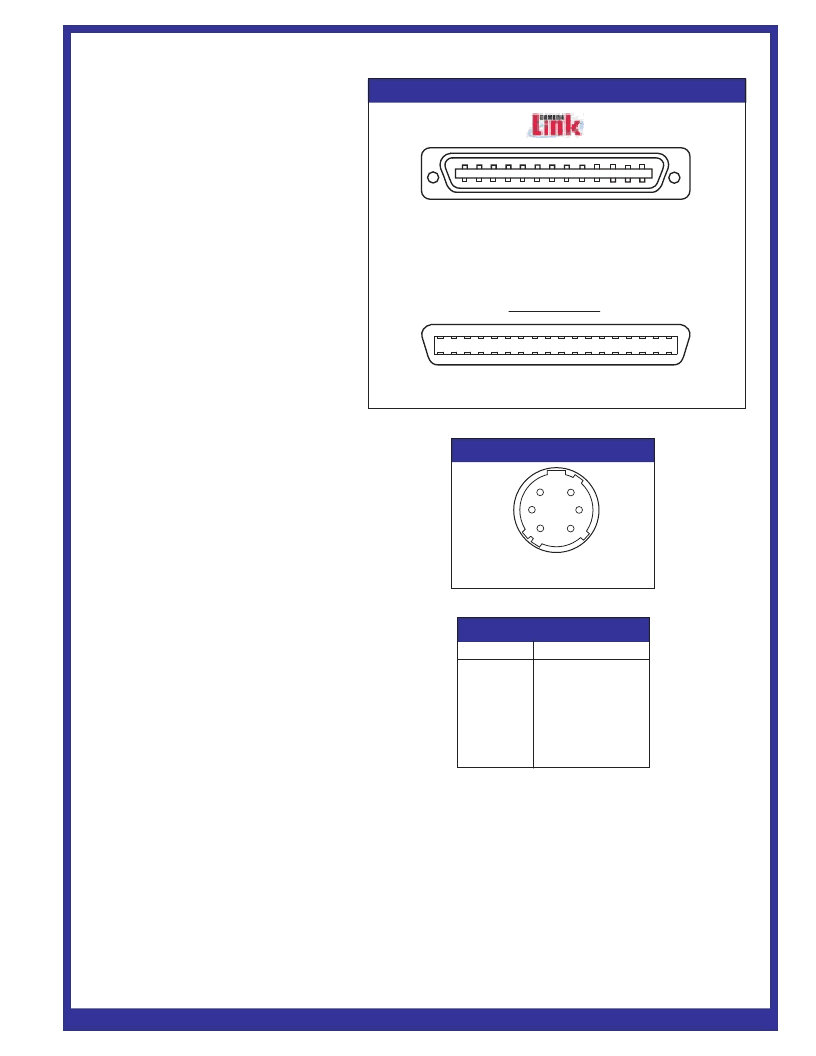
Data and Power Connectors
CameraLink Models:
The communications connector on the
LD3500-series camera is a 26-pin D-type
male connector, common to all CameraLink
applications. This 26-pin connector
contains all communications and controls
needed for camera operation. Power is
provided to the LD3500 via a 6 pin,
Hirose HR10A circular jack. Refer to Table
1a for pinout of the communications and
control connector. Figure 2 provides pinout
locations for this connector.
Figure 2. Connector Diagram
1
2
3
4
5
6
7
8
9
10
11
12
13
14
15
16
17
18
19
20
21
22
23
24
25
26
3M Connector MDR26 Position Plug
Recommended Cable: 3M14X26S2LB-XXX-OLC
1
19
18
36
Recommended Cable: 3M10136-6000EC series
Parallel LVDS
Connector: Hirose HR10A
Mating Part: Hirose HR10A-7P-6S
Figure 3. Power Connector Diagram
5
4
6
2
3
1
PDP-206.01B - 7/2002W Page 3
Pin
1
2
3
4
5
6
Signal
12-24VDC
12-24VDC
Do not connect
Do not connect
Ground
Ground
Table 2. Power Connector Pinout
Note:
The power connector and pinout are
common to all CameraLInk and Parallel
LVDS models
相關(guān)PDF資料 |
PDF描述 |
|---|---|
| LD4000 | PR4/EPR4 Read/Write Controller |
| LD4606A | 30 GHz, 380 W CW, HIGH EFFICIENCY, HIGH POWER GAIN |
| LD502 | Low Distortion AGC Compression Amplifier |
| LD502SLT | Analog IC |
| LD502PLID | Analog IC |
相關(guān)代理商/技術(shù)參數(shù) |
參數(shù)描述 |
|---|---|
| LD3522PGK-011 | 制造商:PERKINELMER 制造商全稱:PerkinElmer Optoelectronics 功能描述:Low-Cost Digital Linescan Camera |
| LD3524 | 制造商:WTE 制造商全稱:Won-Top Electronics 功能描述:35A AVALANCHE LUCAS TYPE PRESS-FIT DIODE |
| LD3541PGK-011 | 制造商:PERKINELMER 制造商全稱:PerkinElmer Optoelectronics 功能描述:Low-Cost Digital Linescan Camera |
| LD3542PGK-011 | 制造商:PERKINELMER 制造商全稱:PerkinElmer Optoelectronics 功能描述:Low-Cost Digital Linescan Camera |
| LD3543PGK-011 | 制造商:PERKINELMER 制造商全稱:PerkinElmer Optoelectronics 功能描述:Low-Cost Digital Linescan Camera |
發(fā)布緊急采購(gòu),3分鐘左右您將得到回復(fù)。