- 您現(xiàn)在的位置:買賣IC網(wǎng) > PDF目錄45001 > LC005B (LINEAGE POWER LLC) DC-DC REG PWR SUPPLY MODULE PDF資料下載
參數(shù)資料
| 型號: | LC005B |
| 廠商: | LINEAGE POWER LLC |
| 元件分類: | 電源模塊 |
| 英文描述: | DC-DC REG PWR SUPPLY MODULE |
| 封裝: | MODULE-5 |
| 文件頁數(shù): | 4/18頁 |
| 文件大小: | 462K |
| 代理商: | LC005B |
12
Lineage Power
Data Sheet
April 2008
18 Vdc to 36 Vdc or 36 Vdc to 75 Vdc Inputs, 5 W
LC/LW005-Series Power Modules:
Thermal Considerations
Sufficient cooling should be provided to help ensure
reliable operation of the power module. Heat-dissipat-
ing components inside the unit are thermally coupled to
the case. Heat is removed by conduction, convection,
and radiation to the surrounding environment. Proper
cooling can be verified by measuring the case temper-
ature. The case temperature (TC) should be measured
at the position indicated in Figure 21.
8-1363(C).a
Note: Dimensions are in millimeters and (inches). Pin locations are
for reference only.
Figure 21. Case Temperature Measurement
Location
Note that the view in Figure 21 is of the surface of the
module—the pin locations shown are for reference.
The temperature at this location should not exceed a
maximum case temperature of 105 °C. The output
power of the module should not exceed the rated
power for the module as listed in the Ordering Informa-
tion table.
The LC/LW005-Series Power Modules operate at
IO = IO, max in an 85 °C ambient temperature with
0.25 ms–1 (50 ft./min.) airflow. This airflow is present in
a typical circuit pack environment in a natural cooled
equipment rack, with other components causing airflow
through the chimney effect. In very low airflow environ-
ments, such as small enclosures, the module should
be derated approximately 10 °C at full load. Note that
these are approximations and that actual case temper-
ature measurements in the equipment rack should be
taken to verify the case temperature does not exceed
105 °C.
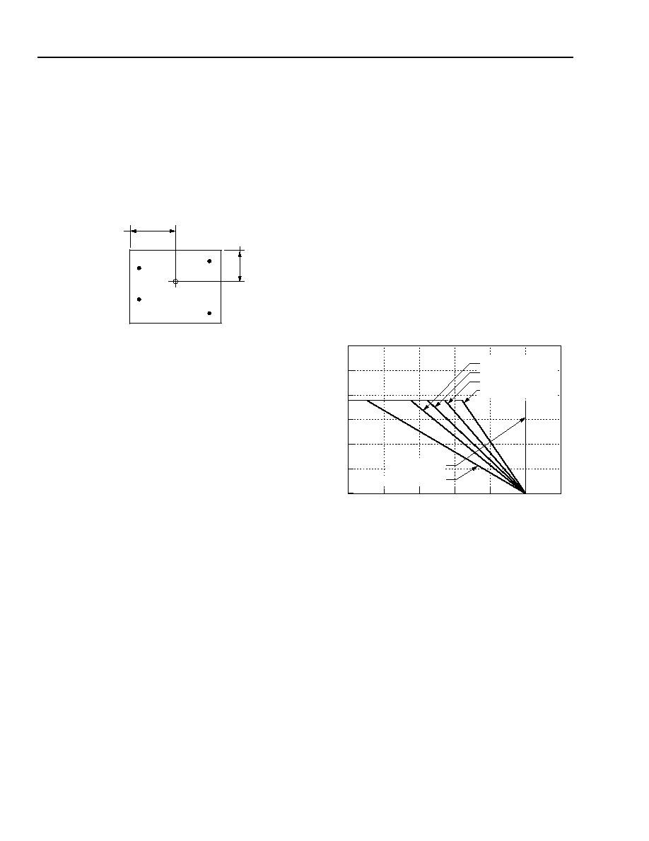
Heat Transfer Characteristics
Increasing airflow over the module enhances the heat
transfer via convection. Figure 22 shows the maximum
power that can be dissipated by the module without
exceeding the maximum case temperature versus local
ambient temperature (TA) for natural convection
through 3.0 ms–1 (600 ft./min.).
Systems in which these power modules are used typi-
cally generate natural convection airflow rates of
0.25 ms–1 (50 ft./min.) due to other heat dissipating
components in the system. Therefore, the natural con-
vection condition represents airflow rates of approxi-
shown in the following example.
Example
What is the minimum airflow necessary for an LW005A
operating at 75 V, an output current of 1 A, and a maxi-
mum ambient temperature of 90 °C?
Solution:
Given: VI = 75 V, IO = 1 A (IO, max), TA = 90 °C
Determine airflow (Figure 22): v = 1.0 ms–1
(200 ft./min.)
8-2623(C)
Figure 22. LC/LW005-Series Forced Convection
Power Derating
dc-dcPOWER
MODULE
16.0(0.63)
+
-
+
-
OUT
IN
10.0
(0.40
85
90
95
100
105
110
0.0
2.5
1.5
1.0
2.0
80
3.0
0.5
MAX AMBIENT TEMPERATURE,TA (
C)
PO
WER
DISSIP
A
TION,
P
D
(W)
NATURAL CONVECTION
3.0 ms-1(600 ft/min)
2.0 ms-1(400 ft/min)
1.5 ms-1(300 ft/min)
1.0 ms-1(200 ft/min)
MAX CASE
TEMPERATURE
相關(guān)PDF資料 |
PDF描述 |
|---|---|
| LC005F | DC-DC REG PWR SUPPLY MODULE |
| LW010F | 1-OUTPUT 8 W DC-DC REG PWR SUPPLY MODULE |
| LC010CL | 2-OUTPUT 15 W DC-DC REG PWR SUPPLY MODULE |
| LC015B | 1-OUTPUT 15 W DC-DC REG PWR SUPPLY MODULE |
| LW010A | 1-OUTPUT 10 W DC-DC REG PWR SUPPLY MODULE |
相關(guān)代理商/技術(shù)參數(shù) |
參數(shù)描述 |
|---|---|
| LC010 | 制造商:MA-COM 制造商全稱:M/A-COM Technology Solutions, Inc. 功能描述:Power Modules: 18 Vdc to 36 Vdc or 36 Vdc to 75 Vdc Inputs, 10 W and 15 W |
| LC010A | 功能描述:DC/DC轉(zhuǎn)換器 5V 2A 10W 6-Pin RoHS:否 制造商:Murata 產(chǎn)品: 輸出功率: 輸入電壓范圍:3.6 V to 5.5 V 輸入電壓(標(biāo)稱): 輸出端數(shù)量:1 輸出電壓(通道 1):3.3 V 輸出電流(通道 1):600 mA 輸出電壓(通道 2): 輸出電流(通道 2): 安裝風(fēng)格:SMD/SMT 封裝 / 箱體尺寸: |
| LC010A2 | 功能描述:DC/DC轉(zhuǎn)換器 STEP DWN 24Vin 2-PIN RoHS:否 制造商:Murata 產(chǎn)品: 輸出功率: 輸入電壓范圍:3.6 V to 5.5 V 輸入電壓(標(biāo)稱): 輸出端數(shù)量:1 輸出電壓(通道 1):3.3 V 輸出電流(通道 1):600 mA 輸出電壓(通道 2): 輸出電流(通道 2): 安裝風(fēng)格:SMD/SMT 封裝 / 箱體尺寸: |
| LC010AJ | 制造商:MA-COM 制造商全稱:M/A-COM Technology Solutions, Inc. 功能描述:Power Modules: 18 Vdc to 36 Vdc or 36 Vdc to 75 Vdc Inputs, 10 W and 15 W |
發(fā)布緊急采購,3分鐘左右您將得到回復(fù)。