- 您現(xiàn)在的位置:買賣IC網(wǎng) > PDF目錄358737 > LA76832N (Sanyo Electric Co.,Ltd.) Monolithic Linear IC I2C Bus Control IC PDF資料下載
參數(shù)資料
| 型號(hào): | LA76832N |
| 廠商: | Sanyo Electric Co.,Ltd. |
| 英文描述: | Monolithic Linear IC I2C Bus Control IC |
| 中文描述: | 單片線性集成電路I2C總線控制IC |
| 文件頁數(shù): | 8/39頁 |
| 文件大小: | 398K |
| 代理商: | LA76832N |
第1頁第2頁第3頁第4頁第5頁第6頁第7頁當(dāng)前第8頁第9頁第10頁第11頁第12頁第13頁第14頁第15頁第16頁第17頁第18頁第19頁第20頁第21頁第22頁第23頁第24頁第25頁第26頁第27頁第28頁第29頁第30頁第31頁第32頁第33頁第34頁第35頁第36頁第37頁第38頁第39頁
LA76832N
No.0069-8/39
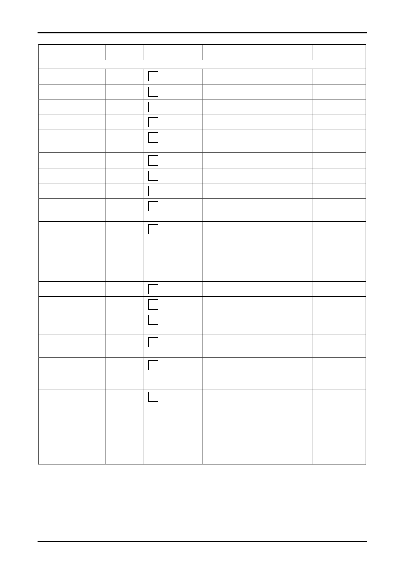
Parameter
Symbol
Test
point
Input
signal
Test method
Bus conditions
[VIF block]
Maximum RF AGC voltage
VRFH
4
SG1
80dB
μ
SG1
80dB
μ
SG1
Measure the DC voltage at pin 4.
RF. AGC = ”000000”
Minimum RF AGC voltage
VRFL
4
Measure the DC voltage at pin 4.
RF. AGC = ”111111”
RF AGC Delay Pt
(@DAC = 0)
RF AGC Delay Pt
(@DAC = 63)
Input sensitivity
RFAGC0
4
Obtain the input level at which the DC voltage at
pin 4 becomes 4.5V.
Obtain the input level at which the DC voltage at
pin 4 becomes 4.5V.
Using an oscilloscope, observe the level at pin
46 and obtain the input level at which the
waveform's p-p value becomes 1.4Vp-p.
Set IF AGC = “1” and measure the DC voltage at
pin 46.
Measure the DC voltage at pin 46.
RF. AGC = ”000000”
RFAGC63
4
SG1
RF. AGC = ”111111”
Vi
46
SG6
No-signal video output
voltage
Sync signal tip level
VOn
46
No signal
VOtip
46
SG1
80dB
μ
SG6
80dB
μ
SG1
80dB
μ
Video output amplitude
VO
46
Using an oscilloscope, observe the level at pin
46 and measure the waveform’s p-p value.
Measure the noise voltage (Vsn) at pin 46 with
an RMS voltmeter through a 10kHz to 4.2MHz
band-pass filter and calculate 20Log (1.43/Vsn).
Input a 80dB
μ
SG1 signal and measure the
DC voltage (V3) at pin 3. Mix SG1 = 74dB
μ
,
SG2 = 64dB
μ
, and SG3 = 64dB
μ
to enter the
mixture in the VIF IN. Apply V3 to pin 3 from an
external DC power supply. Using a spectrum
analyzer, measure the difference between pin
46’s 3.58MHz component and 920MHz
component.
Using a vector scope, measure the level at
Pin 46.
Using a vector scope, measure the level at
Pin 46.
Set and input the SG4 frequency to 44.75MHz to
be input. Measure the DC voltage at pin 10 at
that moment.
Set and input the SG4 frequency to 46.75MHz to
be input. Measure the DC voltage at pin 10 at
that moment.
Adjust the SG4 frequency and measure
frequency deviation
f when the DC voltage at
pin 10 changes from 1.5V to 3.5V.
VAFTS = 2000/
f [mV/kHz]
Connect an oscilloscope to pin 46 and adjust the
SG4 frequency to a frequency higher than
45.75MHz to bring the PLL into unlocked mode.
(A beat signal appears.) Lower the SG4
frequency and measure the frequency at which
the PLL locks again. In the same manner, adjust
the SG4 frequency to a lower frequency to bring
the PLL into unlocked mode. Lower the SG4
frequency and measure the frequency at which
the PLL locks again.
Video S/N
S/N
46
C-S beat level
IC-S
46
SG1
SG2
SG3
Differential gain
DG
46
SG5
80dB
μ
SG5
80dB
μ
SG4
80dB
μ
Differential phase
DP
46
Maximun AFT
output voltage
VAFTH
10
Minimun AFT
output voltage
VAFTL
10
SG4
80dB
μ
z
AFT detection sensitivity
VAFTS
10
SG4
80dB
μ
z
APC pull-in range (U), (L)
fPU, fPL
46
SG4
80dB
μ
相關(guān)PDF資料 |
PDF描述 |
|---|---|
| LA76835NM | Monolithic Linear IC I2C Bus Control IC |
| LA76843N | Monolithic Linear IC I2C Bus Control IC |
| LA76850 | Monolithic Linear IC Black & White Television IC |
| LA7685J | PAL/NTSC Single-chip Color Television Signal Processing Circuit |
| LA7688 | Single-Chip CTV Signal-Processing Circuit for PAL and NTSC Formats |
相關(guān)代理商/技術(shù)參數(shù) |
參數(shù)描述 |
|---|---|
| LA76835NM | 制造商:SANYO 制造商全稱:Sanyo Semicon Device 功能描述:Monolithic Linear IC I2C Bus Control IC |
| LA76835NM_07 | 制造商:SANYO 制造商全稱:Sanyo Semicon Device 功能描述:Monolithic Linear IC For PAL/NTSC Color Television Sets VIF/SIF/Y/C/Deflection Implemented in a Single Chip |
| LA76843N | 制造商:SANYO 制造商全稱:Sanyo Semicon Device 功能描述:Monolithic Linear IC I2C Bus Control IC |
| LA76843N_06 | 制造商:SANYO 制造商全稱:Sanyo Semicon Device 功能描述:I2C Bus Control IC |
| LA76846M-TBM-E | 制造商:SANYO Semiconductor Co Ltd 功能描述: |
發(fā)布緊急采購,3分鐘左右您將得到回復(fù)。