- 您現(xiàn)在的位置:買賣IC網(wǎng) > PDF目錄358737 > LA76070 (Sanyo Electric Co.,Ltd.) NTSC Color Television IC PDF資料下載
參數(shù)資料
| 型號(hào): | LA76070 |
| 廠商: | Sanyo Electric Co.,Ltd. |
| 英文描述: | NTSC Color Television IC |
| 中文描述: | NTSC制式彩色電視芯片 |
| 文件頁(yè)數(shù): | 12/27頁(yè) |
| 文件大小: | 308K |
| 代理商: | LA76070 |
第1頁(yè)第2頁(yè)第3頁(yè)第4頁(yè)第5頁(yè)第6頁(yè)第7頁(yè)第8頁(yè)第9頁(yè)第10頁(yè)第11頁(yè)當(dāng)前第12頁(yè)第13頁(yè)第14頁(yè)第15頁(yè)第16頁(yè)第17頁(yè)第18頁(yè)第19頁(yè)第20頁(yè)第21頁(yè)第22頁(yè)第23頁(yè)第24頁(yè)第25頁(yè)第26頁(yè)第27頁(yè)
Video Switch Block - Input Signals and Measurement Conditions
1. Unless otherwise indicated, these measurements are to be performed with no signal applied to PIF IN (pin 10) and
with the D/A converter IF.ACG.SW set to "1".
2. The table below lists the input signals and their labels.
No. 5844-12/27
LA76070
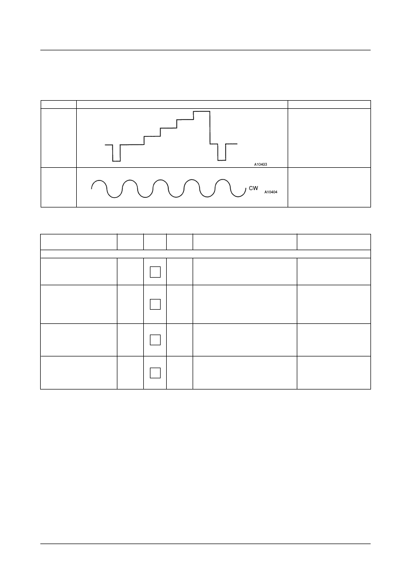
Input signal
Waveform
Condition
SG8
10-step staircase waveform
1 V p-p
SG9
4.2 MHz
1 Vp-p
Parameter
Symbol
Measurement
point
Input signal
Measurement procedure
Bus conditions
[VIF Block]
External video gain
AUXG
Pin 1
SG8
VIDEO.SW = "1"
Observe pin 42 with an oscilloscope and
measure the synchronizing signal tip voltage
in the waveform.
Determine the voltage difference between this
measured value and synchronizing signal tip
level (VOtip) measured in the VIF block.
Measure the 4.2 MHz component in the pin 42
signal with a spectrum analyzer.Convert this
measurement to a V
peak-to-peak
value and
perform the following calculation.
AUXG = 20
×
log (1.4/Vp-p) [dB]
External video sync signal tip
voltage
AUXS
Pin 1
SG8
VIDEO.SW = "1"
Pin 1
SG8
External video crosstalk
AUXC
VIDEO.SW = "0"
Pin 10
SG7
(VIF block)
93 dBμ
Internal video output level
INT0
42
42
42
42
Observe pin 42 with an oscilloscope, measure
the
peak-to-peak
value of the waveform, and
perform the following calculation.
AUXG = 20
×
log (Vp-p) [dB]
Observe pin 45 with an oscilloscope and
measure the
peak-to-peak
value of the
waveform. Determine the difference between
this measured value and the video output
amplitude (VO) measured in the VIF block.
After performing the adjustments
described in section 4
IF. AGC. SW = "0"
VIDEO. SW = "0"
相關(guān)PDF資料 |
PDF描述 |
|---|---|
| LA76075 | NTSC Color Television Sets |
| LA7615 | Single-Chip NTSC Color TV IC |
| LA7620 | Color TV Video, Chroma, Deflection Circuit |
| LA7625 | Video, Chroma and Deflection Circuit for Color Television Sets |
| LA7629 | Color TV/Video,Chroma,Deflection Circuit |
相關(guān)代理商/技術(shù)參數(shù) |
參數(shù)描述 |
|---|---|
| LA76075 | 制造商:SANYO 制造商全稱:Sanyo Semicon Device 功能描述:NTSC Color Television Sets |
| LA7612A | 制造商:SANYO Semiconductor Co Ltd 功能描述: |
| LA7615 | 制造商:SANYO 制造商全稱:Sanyo Semicon Device 功能描述:Single-Chip NTSC Color TV IC |
| LA7620 | 制造商:SANYO 制造商全稱:Sanyo Semicon Device 功能描述:Color TV Video, Chroma, Deflection Circuit |
| LA7621 | 制造商:Panasonic Industrial Company 功能描述:IC |
發(fā)布緊急采購(gòu),3分鐘左右您將得到回復(fù)。