- 您現(xiàn)在的位置:買賣IC網(wǎng) > PDF目錄384585 > L6238SQA (意法半導體) 12V SENSORLESS SPINDLE MOTOR CONTROLLER PDF資料下載
參數(shù)資料
| 型號: | L6238SQA |
| 廠商: | 意法半導體 |
| 英文描述: | 12V SENSORLESS SPINDLE MOTOR CONTROLLER |
| 中文描述: | 12V的無傳感器主軸電機控制器 |
| 文件頁數(shù): | 13/31頁 |
| 文件大?。?/td> | 324K |
| 代理商: | L6238SQA |
第1頁第2頁第3頁第4頁第5頁第6頁第7頁第8頁第9頁第10頁第11頁第12頁當前第13頁第14頁第15頁第16頁第17頁第18頁第19頁第20頁第21頁第22頁第23頁第24頁第25頁第26頁第27頁第28頁第29頁第30頁第31頁
2)
Closed Loop Start-Up
- The Bemf voltage
zerocrossings provide timing information so that
the motor can be accelerated to steady state
speed.
3)
Steady-State Operation
- The Bemf voltage
zero-crossings provide timing information for pre-
cision speed control.
The L6238S contains features that offer flexible
control over the start-up procedure. Either the on-
board Auto-StartAlgorithm can be used to control
the start-up sequence or more sophisticated ex-
tenal start-up algorithms can be developed using
the Serial Port and key control/sense functions
broughtout to pins.
3.2 Auto-Start Algorithm
When initially powered up, the controller defaults
to the internal AutoStart Mode. When
Run/Brake
is low, the L6238S is in brake mode, and the
Auto-Start Algorithm is reset. In the brake mode,
all of the lower DMOS drivers are ON,and the up-
per drivers are OFF.
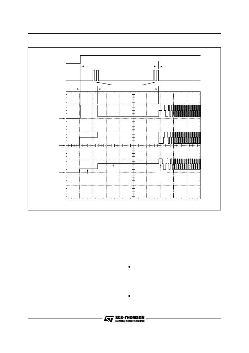
The Auto-Start Algorithm is based on an Align &
Go approachand can be visualized by referring to
Figure 3-1. Shown are the
Run/Brake
control sig-
nals, sequencer function, and the three output
voltage waveforms.
Referring to figure 3-1, the following is the se-
quence of events duringAuto-Start:
With
Output Enable
= 1,
Run/Brake
= 0
- State Machine is set to State 1 with the drivers
Trisatted
.
AlignmentPhase (1)
Run/Brake
= 1
- Output Stage is sequencedto State 2 and the
drivers energized with
OUTPUT A
high and
OUTPUT C
low for 64/Falign seconds.
Alignment Phase (2)
- Output Stage is double sequenced to State 4
with
OUTPUT B
high and
OUTPUT A
low for
STATE 2
A=HIGH
B=FLOAT
C=LOW
STATE 4
A=LOW
B=HIGH
C=FLOAT
STATE 6
A=FLOAT
B=LOW
C=HIGH
500ms/DIV
* FALIGN=90Hz
A
OUT
1
10V
B
OUT
2
10V
C
OUT
3
10V
ALIGNMENT
GO
DOUBLE INCREMENTS
*0.711s
*2.133s
RUN/BRAKE
SEQUENCER
D95IN314
Figure 3-1:
Align+Go
L6238S
13/31
相關(guān)PDF資料 |
PDF描述 |
|---|---|
| L6238SQT | 12V SENSORLESS SPINDLE MOTOR CONTROLLER |
| L6327 | 6 / 4 CHANNEL VOLTAGE SENSE GMR PREAMPLIFIER |
| L6332 | 6 / 4 CHANNEL VOLTAGE SENSE GMR PREAMPLIFIER |
| L6353D | SMART DRIVER FOR POWER MOS & IGBT |
| L6363 | PRML READ/WRITE CHANNEL |
相關(guān)代理商/技術(shù)參數(shù) |
參數(shù)描述 |
|---|---|
| L6238SQT | 制造商:STMICROELECTRONICS 制造商全稱:STMicroelectronics 功能描述:12V SENSORLESS SPINDLE MOTOR CONTROLLER |
| L6239 | 制造商:未知廠家 制造商全稱:未知廠家 功能描述: |
| L623C | 制造商:未知廠家 制造商全稱:未知廠家 功能描述:THYRISTOR MODULE|BRIDGE|HALF-CNTLD|CA|280V V(RRM)|46A I(T) |
| L623F | 制造商:未知廠家 制造商全稱:未知廠家 功能描述:THYRISTOR MODULE|BRIDGE|HALF-CNTLD|CA|280V V(RRM)|46A I(T) |
| L624 | 制造商:CRYDOM 制造商全稱:Crydom Inc., 功能描述:Power Modules |
發(fā)布緊急采購,3分鐘左右您將得到回復。