- 您現(xiàn)在的位置:買賣IC網(wǎng) > PDF目錄97995 > L6238S013TR (STMICROELECTRONICS) BRUSHLESS DC MOTOR CONTROLLER, 5 A, PQCC44 PDF資料下載
參數(shù)資料
| 型號: | L6238S013TR |
| 廠商: | STMICROELECTRONICS |
| 元件分類: | 運動控制電子 |
| 英文描述: | BRUSHLESS DC MOTOR CONTROLLER, 5 A, PQCC44 |
| 封裝: | PLASTIC, LCC-44 |
| 文件頁數(shù): | 26/31頁 |
| 文件大小: | 3465K |
| 代理商: | L6238S013TR |
第1頁第2頁第3頁第4頁第5頁第6頁第7頁第8頁第9頁第10頁第11頁第12頁第13頁第14頁第15頁第16頁第17頁第18頁第19頁第20頁第21頁第22頁第23頁第24頁第25頁當前第26頁第27頁第28頁第29頁第30頁第31頁

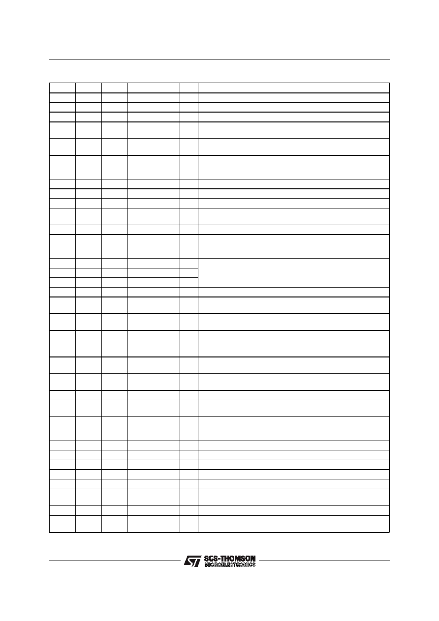
PIN FUNCTIONS
PLCC44 PQFP44 TQFP64
Name
I/O
Function
1
39
56, 57
OUTPUT B
I/O
DMOS Half Bridge Output and Input B for Bemf sensing.
2
40
58
SPIN SENSE
O
Toggless at each Zero Crossing of the Bemf.
3
41
59
BRAKE DELAY
I
Energy Recovery time constant, defined by external R-C to ground.
4
42
60, 61
Rsense 1
O
Outputs A+B connections for the Motor Current Sense Resistor
to ground
5
43
62
CHARGE
PUMP 2
I
Negative Terminal of Pump Capacitor.
6, 7,
17, 29,
39, 40
1, 11,
23, 33,
34, 44
*
GROUND
S
Ground terminals.
8
2
4
CHARGE PUMP 1
I
Positive terminal of Pump Capacitor.
9
3
5
CHARGE PUMP 3
O
Positive terminal of Storage Capacitor.
10
4
6, 7
OUTPUT A
I/O
DMOS Half Bridge Output and Input A for Bemf sensing.
11, 42
5, 36
9, 10,
52, 53
Vpower
S
Power Section Supply Terminal.
12611
Vanalog
S
12V supply.
13, 32
7, 26
8, 18,
19, 31,
41
N.C
Open Terminal
14
8
12
Tdly(0)
I
Three bits that set the Delay between the detection of the Bemf
zero crossing, and the commutation of the next Phase.
15
9
13
Tdly(1)
I
16
10
14
Tdly(2)
I
18
12
20
OTWARN
O
Overtemperature Warning Output
19
13
21
SELECT POLE
I
Selects # of Motor Poles. A zero selects 8, while a one selects 4
poles.
20
14
22
PWM TIMER
I
Capacitor connected to this pin sets the maximum time allowed
for 100% duty cycle during PWM operation
21
15
23
PWM/LINEAR
I
Selects PWM or Linear Output Current Control
22
16
24
OUTPUT
ENABLE
I
Tristates Power Output Stage when a logic zero.
23
17
25
SEQUENCE
I
Rising edge will initiate start-up. A Braking rountine is started
when this input is brought low.
24
18
26
SEQ
INCREMENT
I
A low to high transition on this pin increments the Output State
Sequencer.
25
19
27
SYSTEM CLK
I
Clock Frequency for the system timer/counters.
26
20
28
MONO/SEQ.
INC. CONTROL
I
A logic one will disable the Monotonicity Detector and Sequence
Increment functions.
27
21
29
Falign
I
Reference Frequency for the opt. Auto-Start Algorithm. If int.
start up is not used, this pin must be connected to the System
Clock.
28
22
30
PWM COMP
O
Output of the PWM Comparator
30
24
35
Vlogic
S
5V Logic Supply Voltage.
31
25
36
Fmotor
O
Motor Once-per-Revolution signal.
33
27
37
Vcontrol
I
Voltage at this input controls he Motor Current
34
28
38
CSA INPUT
I
Input to the Current Sense Amplifier.
35
29
39, 40
Rsense 2
O
Output C connection for the Motor Current Sense Resistor to
ground.
36
30
42, 43
OUTPUT C
I/O
DMOS Half Bridge Output and Input C for Bemf sensing.
37
31
44
gm COMP
I
A series RC network to ground that defines the compensation of
the Transconductance Loop.
L6238S
4/31
相關(guān)PDF資料 |
PDF描述 |
|---|---|
| L6246 | VOICE COIL MOTOR CONTROLLER, 3 A, PQFP44 |
| L6258EA | STEPPER MOTOR CONTROLLER, 2 A, PDSO36 |
| L6268 | VOICE COIL MOTOR CONTROLLER, 2.1 A, PQFP44 |
| L6269 | VOICE COIL MOTOR CONTROLLER, 2.1 A, PQFP44 |
| L6280 | STEPPER MOTOR CONTROLLER, 4.4 A, PQCC44 |
相關(guān)代理商/技術(shù)參數(shù) |
參數(shù)描述 |
|---|---|
| L6238SQA | 制造商:STMICROELECTRONICS 制造商全稱:STMicroelectronics 功能描述:12V SENSORLESS SPINDLE MOTOR CONTROLLER |
| L6238SQT | 制造商:STMICROELECTRONICS 制造商全稱:STMicroelectronics 功能描述:12V SENSORLESS SPINDLE MOTOR CONTROLLER |
| L6239 | 制造商:未知廠家 制造商全稱:未知廠家 功能描述: |
| L623C | 制造商:未知廠家 制造商全稱:未知廠家 功能描述:THYRISTOR MODULE|BRIDGE|HALF-CNTLD|CA|280V V(RRM)|46A I(T) |
| L623F | 制造商:未知廠家 制造商全稱:未知廠家 功能描述:THYRISTOR MODULE|BRIDGE|HALF-CNTLD|CA|280V V(RRM)|46A I(T) |
發(fā)布緊急采購,3分鐘左右您將得到回復。