- 您現(xiàn)在的位置:買(mǎi)賣(mài)IC網(wǎng) > PDF目錄43898 > L482D1013TR (STMICROELECTRONICS) SPECIALTY ANALOG CIRCUIT, PDSO16 PDF資料下載
參數(shù)資料
| 型號(hào): | L482D1013TR |
| 廠商: | STMICROELECTRONICS |
| 元件分類(lèi): | 模擬信號(hào)調(diào)理 |
| 英文描述: | SPECIALTY ANALOG CIRCUIT, PDSO16 |
| 封裝: | SO-16 |
| 文件頁(yè)數(shù): | 9/11頁(yè) |
| 文件大?。?/td> | 797K |
| 代理商: | L482D1013TR |
Obsolete
Product(s)
- Obsolete
Product(s)
Obsolete
Product(s)
- Obsolete
Product(s)
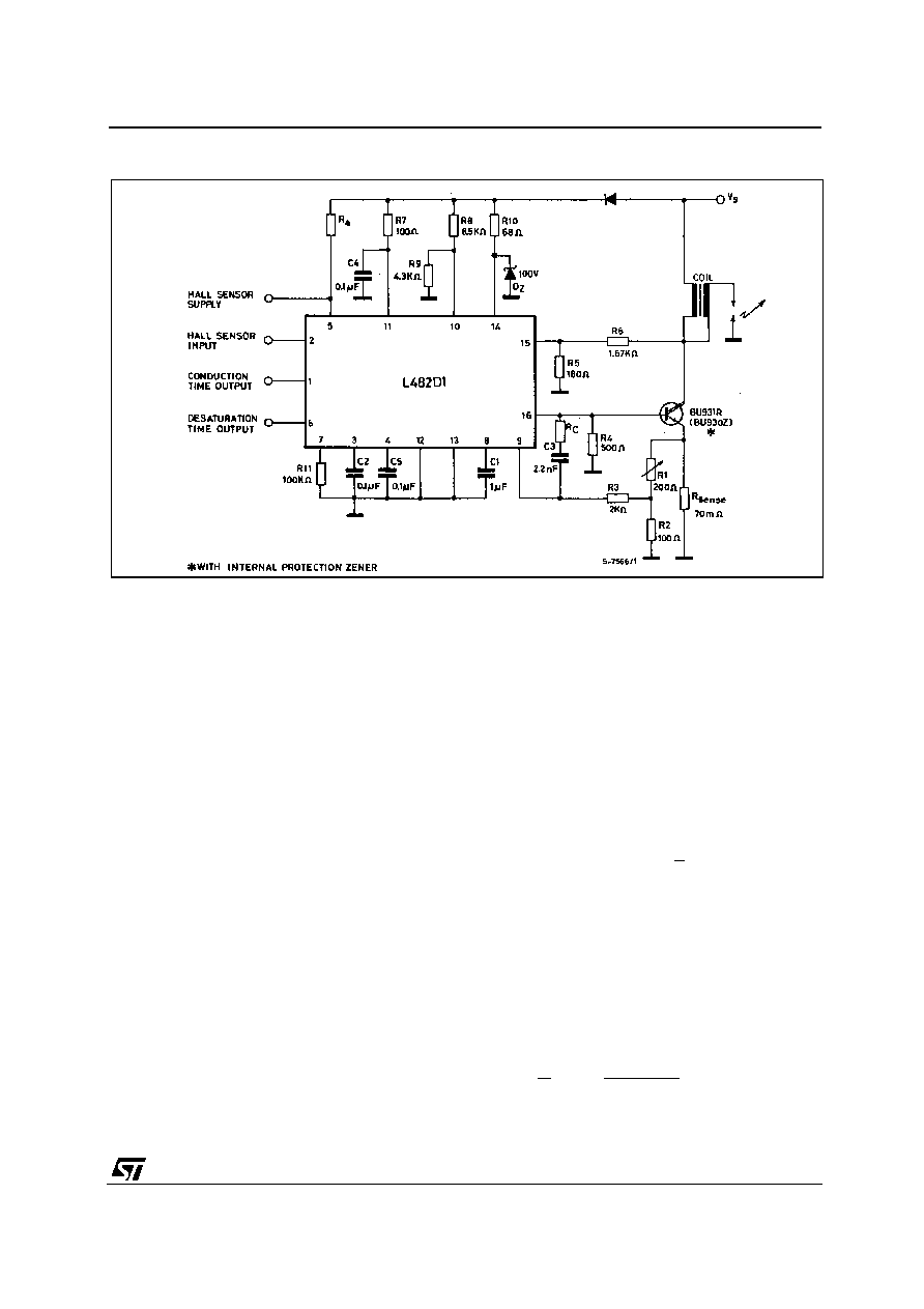
Figure 4 : Application Circuit (SO–16).
CIRCUIT OPERATION
The L482 control the conduction time (dwell) and the
peak value of the primary current in the coil over the
full range of operating conditions.
The coil current is limited to a predetermined level
by means of a negative feedback circuit including a
current sensing resistor, a comparator, the driver
stage and the power switch.
The dwell control circuit maintains the output stage
in its active region during current limitation. The time
the output stage is in the active region (desaturation
time) is sufficient to compensate for possible vari-
ations in the nergy stored due to the acceleration of
the motor ; moreover this time is limited to avoid ex-
cessive power dissipation.
CONTROL OF THE DWELL ANGLE (fig. 1 and 4)
The dwell angle control circuit calculates the con-
duction time D for the output transistor in relation to
the speed of rotation, to the supply voltage and to
the characteristic of the coil.
On the negative edge of the Hall-effect input signal
the capacitor C2 begins discharging with a constant
current I3D. When the set peak value of the coil cur-
rent is reached, this capacitor charges with a con-
stant current I3C = 13.3 x I3D and the coil current is
kept constant by desaturating the driver stage and
the external darlington.
The capacitor C5 starts charging on the positive
edge of the Hall-effect input signal with a constant
current I4C.
The dwell angle, and consequently the starting point
of the coil current production, is decided by the com-
parison between VC2 and VC5. A positive hysteresis
is added to the dwell comparator to avoid spurious
effects and C5 is rapidly discharged on the negative
edge of Hall-effects input signal.
In this way the average voltage on C2 increases if
the motor speed decreases and viceversa in order
to maintain constant the ratiotd at any motor speed.
T
td is kept constant (and not d = cost) to control the
power dissipation and to have sufficient time to
avoid low energy sparks during acceleration.
The charging time D – td depends on the coil and
the voltage supply.
DESATURATION TIMES IN STATIC CONDITION-
S.In static conditions, if C2 = C5 as recommended
and if the values of the application circuit of fig. 3, 4
are used.
td
1
=
T1 + I3C/I3D
L482
7/11
相關(guān)PDF資料 |
PDF描述 |
|---|---|
| L4962EH | 2 A SWITCHING REGULATOR, 120 kHz SWITCHING FREQ-MAX, PZFM7 |
| L4962 | 2 A SWITCHING REGULATOR, 120 kHz SWITCHING FREQ-MAX, PDIP16 |
| L4962/A | 3.3 A SWITCHING REGULATOR, 150 kHz SWITCHING FREQ-MAX, PDIP16 |
| L4963D013TR | 6.5 A SWITCHING REGULATOR, 83 kHz SWITCHING FREQ-MAX, PDSO20 |
| L4963D | 6.5 A SWITCHING REGULATOR, 83 kHz SWITCHING FREQ-MAX, PDSO20 |
相關(guān)代理商/技術(shù)參數(shù) |
參數(shù)描述 |
|---|---|
| L483 | 制造商:未知廠家 制造商全稱(chēng):未知廠家 功能描述:THYRISTOR MODULE|SCR DOUBLER|280V V(RRM)|22A I(T) |
| L-483 | 制造商:KINGBRIGHT 制造商全稱(chēng):Kingbright Corporation 功能描述:T-1 (3mm) CYLINDRICAL LED LAMPS |
| L-483E | 制造商:KINGBRIGHT 制造商全稱(chēng):Kingbright Corporation 功能描述:T-1 (3mm) CYLINDRICAL LED LAMPS |
| L-483ED | 制造商:未知廠家 制造商全稱(chēng):未知廠家 功能描述:1.0x5.0x10.0mm RECTANGULAR LED LAMP |
| L483EDT | 制造商:Kingbright Corporation 功能描述:LED Uni-Color Orange 625nm 2-Pin T-1 3/4 T/R |
發(fā)布緊急采購(gòu),3分鐘左右您將得到回復(fù)。