- 您現(xiàn)在的位置:買賣IC網(wǎng) > PDF目錄3945 > KMPC8314CVRAGDA (Freescale Semiconductor)IC MPU POWERQUICC II 620-PBGA PDF資料下載
參數(shù)資料
| 型號: | KMPC8314CVRAGDA |
| 廠商: | Freescale Semiconductor |
| 文件頁數(shù): | 28/101頁 |
| 文件大小: | 0K |
| 描述: | IC MPU POWERQUICC II 620-PBGA |
| 標準包裝: | 2 |
| 系列: | MPC83xx |
| 處理器類型: | 32-位 MPC83xx PowerQUICC II Pro |
| 速度: | 400MHz |
| 電壓: | 1V |
| 安裝類型: | 表面貼裝 |
| 封裝/外殼: | 620-BBGA 裸露焊盤 |
| 供應(yīng)商設(shè)備封裝: | 620-PBGA(29x29) |
| 包裝: | 托盤 |
第1頁第2頁第3頁第4頁第5頁第6頁第7頁第8頁第9頁第10頁第11頁第12頁第13頁第14頁第15頁第16頁第17頁第18頁第19頁第20頁第21頁第22頁第23頁第24頁第25頁第26頁第27頁當前第28頁第29頁第30頁第31頁第32頁第33頁第34頁第35頁第36頁第37頁第38頁第39頁第40頁第41頁第42頁第43頁第44頁第45頁第46頁第47頁第48頁第49頁第50頁第51頁第52頁第53頁第54頁第55頁第56頁第57頁第58頁第59頁第60頁第61頁第62頁第63頁第64頁第65頁第66頁第67頁第68頁第69頁第70頁第71頁第72頁第73頁第74頁第75頁第76頁第77頁第78頁第79頁第80頁第81頁第82頁第83頁第84頁第85頁第86頁第87頁第88頁第89頁第90頁第91頁第92頁第93頁第94頁第95頁第96頁第97頁第98頁第99頁第100頁第101頁
MPC8314E PowerQUICC II Pro Processor Hardware Specifications, Rev. 2
32
Freescale Semiconductor
Ethernet: Three-Speed Ethernet, MII Management
9.5
SGMII Interface Electrical Characteristics
Each SGMII port features a 4-wire AC-Coupled serial link from the dedicated SerDes interface of
output pin of the SerDes transmitter differential pair features 50-
output impedance. Each input of the
SerDes receiver differential pair features 50-
on-die termination to XCOREVSS. The reference circuit
of the SerDes transmitter and receiver is shown in Figure 48.
When an eTSEC port is configured to operate in SGMII mode, the parallel interface’s output signals of
this eTSEC port can be left floating. The input signals should be terminated based on the guidelines
described in Section 25.4, “Connection Recommendations,” as long as such termination does not violate
the desired POR configuration requirement on these pins, if applicable.
When operating in SGMII mode, the TSEC_GTX_CLK125 clock is not required for this port. Instead,
SerDes reference clock is required on SD_REF_CLK and SD_REF_CLK pins.
9.5.1
DC Requirements for SGMII SD_REF_CLK and SD_REF_CLK
The characteristics and DC requirements of the separate SerDes reference clock are described in
9.5.2
AC Requirements for SGMII SD_REF_CLK and SD_REF_CLK
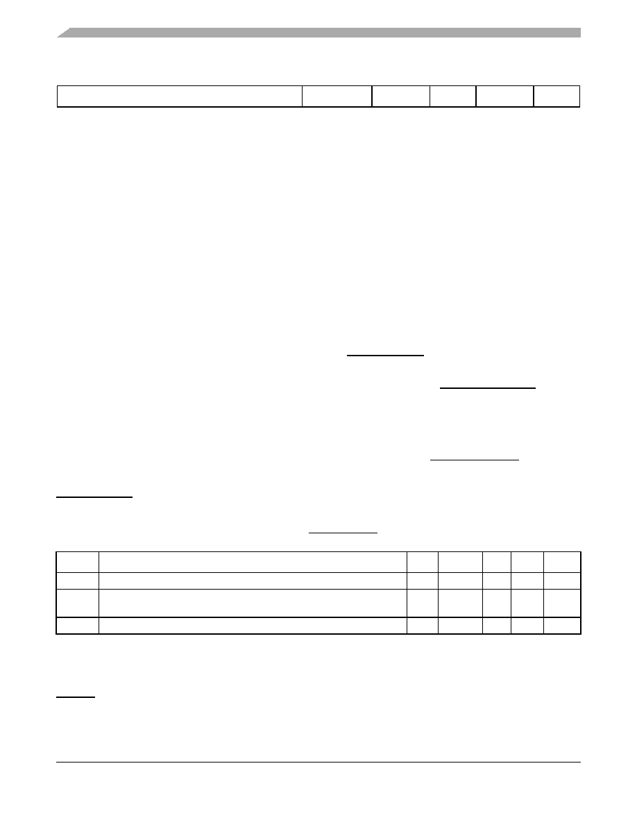
This table lists the SGMII SerDes reference clock AC requirements. Please note that SD_REF_CLK and
SD_REF_CLK are not intended to be used with, and should not be clocked by, a spread spectrum clock
source.
9.5.3
SGMII Transmitter and Receiver DC Electrical Characteristics
characteristics. Transmitter DC characteristics are measured at the transmitter outputs (SD_TX[n] and
SD_TX[n]) as depicted in Figure 16.
Note:
1. The timer can operate on rtc_clock or tmr_clock. These clocks get muxed and any one of them can be selected.
2. Asynchronous signals.
3. Inputs need to be stable at least one TMR clock.
Table 34. SD_REF_CLK and SD_REF_CLK AC Requirements
Symbol
Parameter Description
Min
Typical
Max
Unit
Note
tREF
REFCLK cycle time
—
8
—
ns
—
tREFCJ
REFCLK cycle-to-cycle jitter. Difference in the period of any two adjacent
REFCLK cycles
——
100
ps
—
tREFPJ
Phase jitter. Deviation in edge location with respect to mean edge location
–50
—
50
ps
—
Table 33. 1588 Timer AC Specifications (continued)
Parameter
Symbol
Min
Max
Unit
Note
相關(guān)PDF資料 |
PDF描述 |
|---|---|
| KMPC8313ZQAFFB | IC MPU POWERQUICC II 516-PBGA |
| 2-1734798-7 | CONN HOUSING FPC 27POS R/A SMD |
| 487951-4 | 004 1MM FPC TOP HORZ |
| 3-487951-0 | CONN 1MM FPC 30POS R/A SMD |
| 487576-4 | CONN ZIF LINE 12POS TIN |
相關(guān)代理商/技術(shù)參數(shù) |
參數(shù)描述 |
|---|---|
| KMPC8314ECVRAGDA | 功能描述:微處理器 - MPU ENCRYPT RoHS:否 制造商:Atmel 處理器系列:SAMA5D31 核心:ARM Cortex A5 數(shù)據(jù)總線寬度:32 bit 最大時鐘頻率:536 MHz 程序存儲器大小:32 KB 數(shù)據(jù) RAM 大小:128 KB 接口類型:CAN, Ethernet, LIN, SPI,TWI, UART, USB 工作電源電壓:1.8 V to 3.3 V 最大工作溫度:+ 85 C 安裝風格:SMD/SMT 封裝 / 箱體:FBGA-324 |
| KMPC8314EVRAGDA | 功能描述:微處理器 - MPU ENCRYPT RoHS:否 制造商:Atmel 處理器系列:SAMA5D31 核心:ARM Cortex A5 數(shù)據(jù)總線寬度:32 bit 最大時鐘頻率:536 MHz 程序存儲器大小:32 KB 數(shù)據(jù) RAM 大小:128 KB 接口類型:CAN, Ethernet, LIN, SPI,TWI, UART, USB 工作電源電壓:1.8 V to 3.3 V 最大工作溫度:+ 85 C 安裝風格:SMD/SMT 封裝 / 箱體:FBGA-324 |
| KMPC8314VRAGDA | 功能描述:微處理器 - MPU NON-ENCRYPT RoHS:否 制造商:Atmel 處理器系列:SAMA5D31 核心:ARM Cortex A5 數(shù)據(jù)總線寬度:32 bit 最大時鐘頻率:536 MHz 程序存儲器大小:32 KB 數(shù)據(jù) RAM 大小:128 KB 接口類型:CAN, Ethernet, LIN, SPI,TWI, UART, USB 工作電源電壓:1.8 V to 3.3 V 最大工作溫度:+ 85 C 安裝風格:SMD/SMT 封裝 / 箱體:FBGA-324 |
| KMPC8315CVRAGDA | 功能描述:微處理器 - MPU NON-ENCRYPT RoHS:否 制造商:Atmel 處理器系列:SAMA5D31 核心:ARM Cortex A5 數(shù)據(jù)總線寬度:32 bit 最大時鐘頻率:536 MHz 程序存儲器大小:32 KB 數(shù)據(jù) RAM 大小:128 KB 接口類型:CAN, Ethernet, LIN, SPI,TWI, UART, USB 工作電源電壓:1.8 V to 3.3 V 最大工作溫度:+ 85 C 安裝風格:SMD/SMT 封裝 / 箱體:FBGA-324 |
| KMPC8315ECVRAGDA | 功能描述:微處理器 - MPU ENCRYPT RoHS:否 制造商:Atmel 處理器系列:SAMA5D31 核心:ARM Cortex A5 數(shù)據(jù)總線寬度:32 bit 最大時鐘頻率:536 MHz 程序存儲器大小:32 KB 數(shù)據(jù) RAM 大小:128 KB 接口類型:CAN, Ethernet, LIN, SPI,TWI, UART, USB 工作電源電壓:1.8 V to 3.3 V 最大工作溫度:+ 85 C 安裝風格:SMD/SMT 封裝 / 箱體:FBGA-324 |
發(fā)布緊急采購,3分鐘左右您將得到回復。