- 您現(xiàn)在的位置:買賣IC網(wǎng) > PDF目錄374334 > KH207 (Fairchild Semiconductor Corporation) Low Distortion Wideband Op Amp PDF資料下載
參數(shù)資料
| 型號: | KH207 |
| 廠商: | Fairchild Semiconductor Corporation |
| 英文描述: | Low Distortion Wideband Op Amp |
| 中文描述: | 低失真寬帶運(yùn)算放大器 |
| 文件頁數(shù): | 5/7頁 |
| 文件大小: | 159K |
| 代理商: | KH207 |
KH207
DATA SHEET
REV. 1A February 2001
5
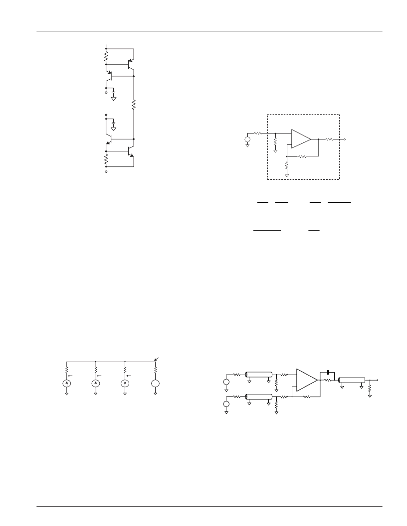
Figure 4: Active Current Limit Circuit (50mA)
Controlling Bandwidth and Passband Response
In most applications, a feedback resistor value of 2k
will provide optimum performance; nonetheless, some
applications may require a resistor of some other value.
The response versus R
f
plot on the previous page shows
how decreasing R
f
will increase bandwidth (and frequency
response peaking, which may lead to instability).
Conversely, large values of feedback resistance tend to
roll off the response.
The best settling time performance requires the use of an
external feedback resistor (use of the internal resistor
results in a 0.1% to 0.2% settling tail). The settling
performance may be improved slightly by adding a
capacitance of 0.4pF in parallel with the feedback
resistor (settling time specifications reflect performance
with an external feedback resistor but with no external
capacitance).
Thermal Model
Noise Analysis
Approximate noise figure can be determined for the
KH207 using the
Equivalent Input Noise
plot on page 3
and the equations shown below.
kT = 4.00 x 10
-21
Joules at 290
°
K
V
n
is spot noise voltage (V/
√
Hz)
i
n
is non-inverting spot noise current (A/
√
Hz)
i
i
is inverting spot noise current (A/
√
Hz)
Figure 5: Noise Figure Diagram and Equations
(Noise Figure is for the Network Inside this Box.)
Driving Cables and Capacitive Loads
When driving cables, double termination is used to
prevent reflections. For capacitive load applications, a
small series resistor at the output of the KH207 will
improve stability and settling performance.
Transmission Line Matching
One method for matching the characteristic impedance
(Z
o
) of a transmission line or cable is to place the
appropriate resistor at the input or output of the amplifier.
Figure 6 shows typical inverting and non-inverting circuit
configurations for matching transmission lines.
Figure 6:Transmission Line Matching
Non-inverting gain applications:
I
Connect R
g
directly to ground.
I
Make R
1
, R
2
, R
6
, and R
7
equal to Z
o
.
I
Use R
3
to isolate the amplifier from reactive
loading caused by the transmission line,
or by parasitics.
R
s
R
n
R
o
R
f
R
g
KH207
-
+
F
R
R
R
4
kT
i
V
R
R
i
R
A
whereR
R
R
+
R
R
A
R
R
s
n
s
n
n
2
p
f
i
p
v
p
s
n
s
n
v
f
g
=
+
+
+
+
=
=
+
10
1
1
2
2
2
2
2
2
log
;
Q3
(2N3906)
R
x
14.3k
Q4
(2N3904)
0.01
F
0.01
F
+V
cc
R
c
12
Q1
(MJE170)
Q2
(MJE180)
R
c
12
-V
cc
to pin 10
to pin 12
P
circuit
= [(+V
CC
)
–
(-V
CC
)]
2
/ 1.77k
P
xxx
= [(±V
)
–
V
–
(I
col
) (R
col
+ 6)] (I
col
)
(% duty cycle)
(For positive V
o
and V
CC
, this is the power in the npn output stage.)
(For negative V
o
and V
CC
, this is the power in the pnp output stage.)
θ
ca
= 65
°
C/W in still air without a heatsink.
35
°
C/W in still air without a Thermalloy 2268.
15
°
C/W in 300ft/min air with a Thermalloy 2268
(Thermalloy 2240 works equally well.)
I
col
= V
/R
or 3mA, whichever is greater.
(Include feedback R in R
load
.)
R
col
is a resistor (33
recommended) between the xxx collector and ±V
CC
.
T
j (pnp)
= P
pnp
(100 +
θ
ca
) + (P
cir
+ P
npn
)
θ
ca
+ T
a
, similar for T
j (npn)
.
T
j (cir)
= P
cir
(17.5 +
θ
ca
) + (P
pnp
+ P
npn
)
θ
ca
+ T
a
.
+
-
T
ambient
θ
ca
T
case
17.5
°
C/W
T
j(circuit)
P
circuit
100
°
C/W
T
j(npn)
P
npn
100
°
C/W
P
pnp
T
j(pnp)
KH207
-
+
R
3
Z
0
R
6
V
o
Z
0
R
1
R
2
+
R
g
Z
0
R
4
R
5
V
1
V
2
+
R
f
C
6
R
7
相關(guān)PDF資料 |
PDF描述 |
|---|---|
| KH220 | Fast Settling Wideband Op Amp |
| KH231 | Fast Settling, Wideband Buffer/Amplifier (Av = 【1 to 【5) |
| KH232 | Low Distortion Wideband Op Amp |
| KH300 | Wideband, High-Speed Operational Amplifier |
| KH560 | Wideband, Low Distortion Driver Amplifier |
相關(guān)代理商/技術(shù)參數(shù) |
參數(shù)描述 |
|---|---|
| KH20701-1V | 制造商:ITT Interconnect Solutions 功能描述:KH20701-1V - Bulk |
| KH20701-3X | 制造商:ITT Interconnect Solutions 功能描述:KH20701-3X - Bulk |
| KH20701-5Z | 制造商:ITT Interconnect Solutions 功能描述:KH20701-5Z - Bulk |
| KH207AI | 功能描述:運(yùn)算放大器 - 運(yùn)放 OP AMP WIDEBAND 2400 V/us 170MHz 3MOHM RoHS:否 制造商:STMicroelectronics 通道數(shù)量:4 共模抑制比(最小值):63 dB 輸入補(bǔ)償電壓:1 mV 輸入偏流(最大值):10 pA 工作電源電壓:2.7 V to 5.5 V 安裝風(fēng)格:SMD/SMT 封裝 / 箱體:QFN-16 轉(zhuǎn)換速度:0.89 V/us 關(guān)閉:No 輸出電流:55 mA 最大工作溫度:+ 125 C 封裝:Reel |
| KH207AK | 制造商:CADEKA 制造商全稱:CADEKA 功能描述:Low Distortion Wideband Op Amp |
發(fā)布緊急采購,3分鐘左右您將得到回復(fù)。