- 您現(xiàn)在的位置:買(mǎi)賣(mài)IC網(wǎng) > PDF目錄374267 > K4H643238D-TLA2 (SAMSUNG SEMICONDUCTOR CO. LTD.) 128Mb DDR SDRAM PDF資料下載
參數(shù)資料
| 型號(hào): | K4H643238D-TLA2 |
| 廠(chǎng)商: | SAMSUNG SEMICONDUCTOR CO. LTD. |
| 英文描述: | 128Mb DDR SDRAM |
| 中文描述: | 128MB DDR SDRAM的 |
| 文件頁(yè)數(shù): | 43/53頁(yè) |
| 文件大?。?/td> | 669K |
| 代理商: | K4H643238D-TLA2 |
第1頁(yè)第2頁(yè)第3頁(yè)第4頁(yè)第5頁(yè)第6頁(yè)第7頁(yè)第8頁(yè)第9頁(yè)第10頁(yè)第11頁(yè)第12頁(yè)第13頁(yè)第14頁(yè)第15頁(yè)第16頁(yè)第17頁(yè)第18頁(yè)第19頁(yè)第20頁(yè)第21頁(yè)第22頁(yè)第23頁(yè)第24頁(yè)第25頁(yè)第26頁(yè)第27頁(yè)第28頁(yè)第29頁(yè)第30頁(yè)第31頁(yè)第32頁(yè)第33頁(yè)第34頁(yè)第35頁(yè)第36頁(yè)第37頁(yè)第38頁(yè)第39頁(yè)第40頁(yè)第41頁(yè)第42頁(yè)當(dāng)前第43頁(yè)第44頁(yè)第45頁(yè)第46頁(yè)第47頁(yè)第48頁(yè)第49頁(yè)第50頁(yè)第51頁(yè)第52頁(yè)第53頁(yè)
- 43 -
REV. 1.0 November. 2. 2000
128Mb DDR SDRAM
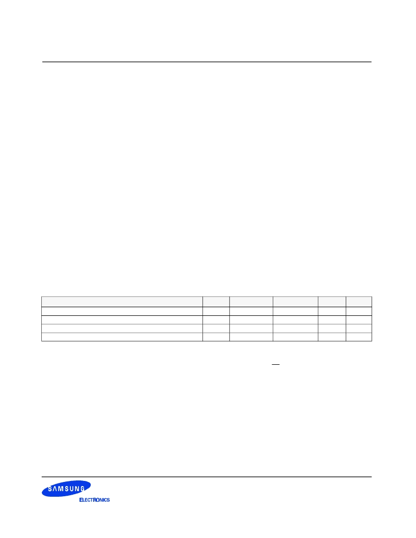
8. AC Operating Conditions & Timming Specification
8.1 AC Operating Conditions
Parameter/Condition
Symbol
Min
Max
Unit
Note
Input High (Logic 1) Voltage, DQ, DQS and DM signals
Input Low (Logic 0) Voltage, DQ, DQS and DM signals.
Input Differential Voltage, CK and CK inputs
Input Crossing Point Voltage, CK and CK inputs
VIH(AC)
VIL(AC)
VID(AC)
VIX(AC)
VREF + 0.31
V
V
V
V
1
2
3
4
VREF - 0.31
VDDQ+0.6
0.5*VDDQ+0.2
0.62
0.5*VDDQ-0.2
Note 1. Vih(max) = 4.2V. The overshoot voltage duration is
≤
3ns at VDD.
2. Vil(min) = -1.5V. The undershoot voltage duration is
≤
3ns at VSS.
3. VID is the magnitude of the difference between the input level on CK and the input on CK.
4. The value of V
IX
is expected to equal 0.5*V
DDQ
of the transmitting device and must track variations in the DC level of the same.
Table 13. AC operating conditions
I
DD7
: Operating current: Four bank operation
1. Typical Case : Vdd = 2.5V, T=25’C
2. Worst Case : Vdd = 2.7V, T= 10’C
3. Four banks are being interleaved with tRC(min), Burst Mode, Address and Control inputs on NOP edge are not
changing. lout = 0mA
4. Timing patterns
- DDR200(100Mhz, CL=2) : tCK = 10ns, CL2, BL=4, tRRD = 2*tCK, tRCD= 3*tCK, Read with autoprecharge
Read : A0 N A1 R0 A2 R1 A3 R2 A0 R3 A1 R0 - repeat the same timing with random address changing
*50% of data changing at every burst
- DDR266B(133Mhz, CL=2.5) : tCK = 7.5ns, CL=2.5, BL=4, tRRD = 2*tCK, tRCD = 3*tCK
Read with autoprecharge
Read : A0 N A1 R0 A2 R1 A3 R2 N R3 A0 N A1 R0 - repeat the same timing with random address changing
*50% of data changing at every burst
- DDR266A (133Mhz, CL=2) : tCK = 7.5ns, CL2=2, BL=4, tRRD = 2*tCK, tRCD = 3*tCK
Read : A0 N A1 R0 A2 R1 A3 R2 N R3 A0 N A1 R0 - repeat the same timing with random address changing
*50% of data changing at every burst
Legend : A=Activate, R=Read, W=Write, P=Precharge, N=NOP
相關(guān)PDF資料 |
PDF描述 |
|---|---|
| K4H643238D-TLB0 | 128Mb DDR SDRAM |
| K4H643238E-TCA0 | 128Mb DDR SDRAM |
| K4H643238E-TCA2 | 128Mb DDR SDRAM |
| K4H643238E-TCB0 | 128Mb DDR SDRAM |
| K4H563238C-TLA0 | 10-Bit, 164 kSPS ADC Parallel Out, Direct I/F to DSP/uProcessor, 10 Ch. 28-PLCC -40 to 85 |
相關(guān)代理商/技術(shù)參數(shù) |
參數(shù)描述 |
|---|---|
| K4H643238D-TLB0 | 制造商:SAMSUNG 制造商全稱(chēng):Samsung semiconductor 功能描述:128Mb DDR SDRAM |
| K4H643238E-TCA0 | 制造商:SAMSUNG 制造商全稱(chēng):Samsung semiconductor 功能描述:128Mb DDR SDRAM |
| K4H643238E-TCA2 | 制造商:SAMSUNG 制造商全稱(chēng):Samsung semiconductor 功能描述:128Mb DDR SDRAM |
| K4H643238E-TCB0 | 制造商:SAMSUNG 制造商全稱(chēng):Samsung semiconductor 功能描述:128Mb DDR SDRAM |
| K4H643238E-TLA0 | 制造商:SAMSUNG 制造商全稱(chēng):Samsung semiconductor 功能描述:128Mb DDR SDRAM |
發(fā)布緊急采購(gòu),3分鐘左右您將得到回復(fù)。