- 您現(xiàn)在的位置:買賣IC網(wǎng) > PDF目錄374254 > K3NC-NB1A (Omron Electronics LLC) Up/Down Counting Meter PDF資料下載
參數(shù)資料
| 型號: | K3NC-NB1A |
| 廠商: | Omron Electronics LLC |
| 英文描述: | Up/Down Counting Meter |
| 中文描述: | 上/下計(jì)數(shù)儀 |
| 文件頁數(shù): | 6/23頁 |
| 文件大?。?/td> | 669K |
| 代理商: | K3NC-NB1A |
C-136
Up/Down Counting Meter
K3NC
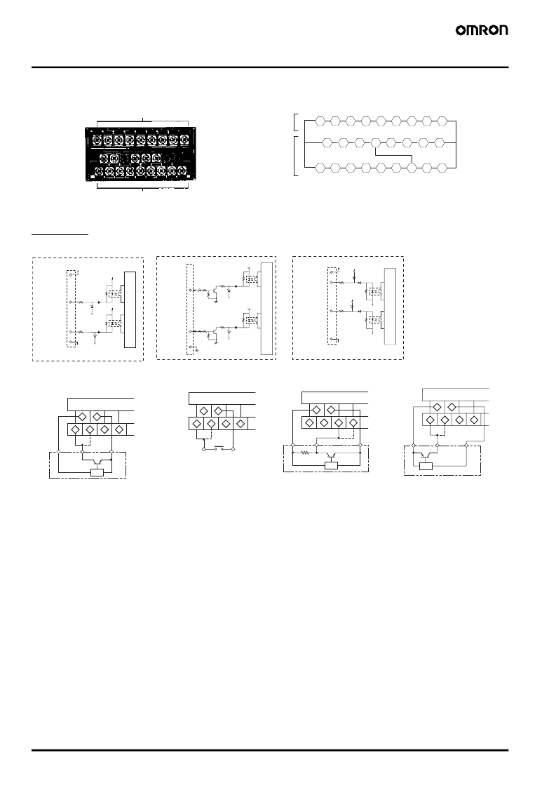
Connections
I
Terminal Arrangement
Input Unit
18 19 20 21 22 23 24 25 26
10
11
12
13 14
15
16
17
1
2
3
4
5
6
7
8
9
Terminal Numbers
Output unit
Input unit
Output
unit
Input
unit
Note:
Terminals 7 to 13 are connected internally.
Terminals 7 and 11 are mutually isolated.
+12 V
+12 V
590
590
820
820
+12 V
10
1
2
11
GND
GND
+12 V
590
820
3
GND
10 k
+12 V
590
820
4
11
GND
10 k
+12 V
+12 V
590
820
10
1
2
11
GND
GND
GND
590
820
External
sensor
power
Input A
Input B
External
sensor
power
)
I
Voltage Pulse Inputs
Input A
Input B
I
PNP-input Models
External
power
supply (+)
Input A
Input B
External
sensor
power
)
I
NPN Inputs
10
11
1
2
3
4
+12 V
INA
INB
0 V
10
11
1
2
3
4
INA
INB
GND
10
11
1
2
3
4
+12V
INA
INB
0 V
+12V
INA
INB
0 V
10
11
1
2
3
4
Contact
NPN output sensor
PNP output sensor
Contact Output
Voltage Output
PNP Open Collector Output
NPN Open Collector Output
(NPN Linear 2-wire Output)
Note:
Connect the + side of the NPN
linear 2-wire input to terminal 1
and the
side to terminal 11.
Note:
With voltage pulse input
not from a 3-wire sensor,
connect the + side to ter-
minal 3 and the
side to
terminal 11.
Note:
When the contact is short-
circuited, a current of approxi-
mately 13 mA will flow at a volt-
age of approximately 12 V.
Input resistance: 10 k
Voltage pulse output sensor
相關(guān)PDF資料 |
PDF描述 |
|---|---|
| K3NC-NB1C | Up/Down Counting Meter |
| K3NC-NB2A | Up/Down Counting Meter |
| K3NC-NB2C | Up/Down Counting Meter |
| K3NC-PB1A | Up/Down Counting Meter |
| K3NC-PB1C | Up/Down Counting Meter |
相關(guān)代理商/技術(shù)參數(shù) |
參數(shù)描述 |
|---|---|
| K3NCNB1C | 功能描述:控制器 Use K3HB-C RoHS:否 制造商:Omron Industrial 模擬/數(shù)字:Digital 類型:Digital Temperature Controller 顯示器類型:11-Segment, 4 Digit 電源電壓:100 VAC to 240 VAC 安裝: 控制方法: 大小:48 mm x 48 mm |
| K3NC-NB1C | 制造商:OMRON 制造商全稱:Omron Electronics LLC 功能描述:Up/Down Counting Meter |
| K3NCNB2A | 制造商:OMRON INDUSTRIAL AUTOMATION 功能描述:Up/Down Counting Meter |
| K3NC-NB2A | 功能描述:通用繼電器 UP/DOWN COUNT METER RoHS:否 制造商:Omron Electronics 觸點(diǎn)形式:1 Form A (SPST-NO) 觸點(diǎn)電流額定值:150 A 線圈電壓:24 VDC 線圈電阻:144 Ohms 線圈電流:167 mA 切換電壓:400 V 安裝風(fēng)格:Chassis 觸點(diǎn)材料: |
| K3NCNB2C | 制造商:OMRON INDUSTRIAL AUTOMATION 功能描述:Up/Down Counting Meter |
發(fā)布緊急采購,3分鐘左右您將得到回復(fù)。