- 您現(xiàn)在的位置:買賣IC網(wǎng) > PDF目錄384532 > ISL9206_07 (Intersil Corporation) FlexiHash+ For Battery Authentication PDF資料下載
參數(shù)資料
| 型號: | ISL9206_07 |
| 廠商: | Intersil Corporation |
| 英文描述: | FlexiHash+ For Battery Authentication |
| 中文描述: | FlexiHash對于電池認證 |
| 文件頁數(shù): | 5/17頁 |
| 文件大?。?/td> | 341K |
| 代理商: | ISL9206_07 |
5
FN9260.2
January 5, 2007
Theory of Operation
The ISL9206 contains all circuitry required to support battery
pack authentication based on a challenge-response
scheme. It provides a 16-Byte One-Time Programmable
Read-Only Memory (OTPROM) space for the storage of up
to 96-Bit of secret for the authentication and other user
information. A 32-Bit hash engine (FlexiHash+) calculates
the authentication result immediately after receiving a 32-Bit
random challenge code. The communication between the
ISL9206 and the host is implemented through the XSD
single-wire communication bus.
Major functions within the ISL9206 include the following, as
shown in Figure 3.
Power-on reset (POR) and a 2.5V regulator to power all
internal logic circuits.
16 x 8-Bit (16-Byte) OTP ROM as shown in Table 8. The
first part (two bytes) contains the device default
configuration (DCFG) information (such as the device
address and the XSD communication speed) and the
default trimming (DTRM) information (such as the internal
oscillator frequency trimming). The second part contains
two groups (12-Byte) of memory that can be
independently locked out for the storage of up to three
sets of secret. The last part provides two additional bytes
of space for general-purpose information.
Control functions, including master control (MSCR) and
status (STAT) registers (as shown in Table 9), interrupt
generation, and the test-related interface.
FlexiHash+ engine that includes the 32-Bit highly non-
linear proprietry hash engine, secret selection register,
challenge code register, and the authentication result
register. Table 10 shows all the registers.
XSD communication bus Interface. The XSD device
address and the communication speed are configured in
the DCFG address in the OTPROM, as given in Table 8.
Time Base Reference.
The following explain in detail the operation of the ISL9206.
Power-On Reset (POR)
The ISL9206 powers up in Sleep mode. It remains in Sleep
mode until a power-on ‘break’ command is received from the
host through the XSD bus. The initial power-on ’break’ can
be of any pulse width as long as it is wider than the XSD
input deglitch time (20
μ
s). Once the ‘break’ command is
received, the internal regulator is powered up. About 20
μ
s
after the falling edge of the power-on ‘break’, an internal
POR circuit releases the reset to the digital block, and a
POR sequence is started. During the POR sequence, the
ISL9206 initializes itself by loading the default device
configuration information from pre-assigned locations within
the OTP ROM memory. After initialization, a ‘break’
command is returned to the host to indicate that the ISL9206
is ready and waiting for a bus transaction from the host.
Note that the ISL9206 will initiate the power-on sequence
without waiting for the power-on ‘break’ signal to return to
the high state. If the host sends an initial ‘break’ pulse wider
than 60
μ
s, the device-ready ‘break’ returned by the ISL9206
will likely be merged with the pulse sent by the host and,
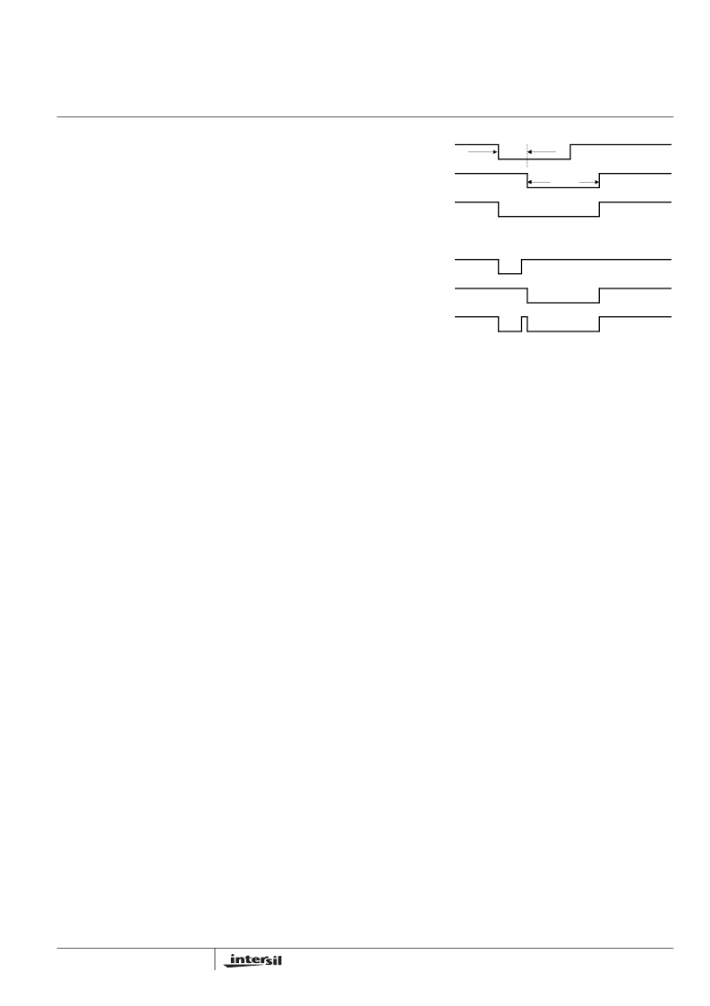
therefore, may not be detectable. Figure 4 illustrates the
waveforms during the Power-on Reset. Figure 4 (A)
represents the case when the power-on ‘break’ rising edge
occurs after the device starts sending the ‘break’. Figure 4
(B) represents the case when the power-on ‘break’ finishes
before the device sends its ‘break’. The device break signal
is always 1.391 times of the device bit-time (BT, see XSD
Bus Interface section for more details). Either case in Figure
4 will wake up the device successfully if the device is in the
sleep mode.
It is important to keep in mind that a narrow ‘break’ signal will
be taken as a normal bit signal and cause errors, if the
device is not in the sleep mode.
For this reason, the narrow
power-on ‘break’ signal should be used only if the user has
to see the returned ‘break’ signal.
Auto-Sleep
While the ISL9206 is powered up and there is no bus activity
for more than about 1 second, the device will automatically
return to Sleep mode. Sleep mode can be entered
independent of whether the XSD bus is held high or low.
While the ISL9206 is in Sleep mode, it is recommended that
the XSD bus be held low to eliminate current drain through
the XSD-pin internal pull-down current.
Auto-Sleep mode can be disabled by clearing the ASLP bit
in the MSCR register. By default, Auto-Sleep is always
enabled at power-up and after a soft reset. Auto-sleep
function can be permanently disabled by clearing the 0-00[2]
bit (the ASLP bit in DCFG) during OTP ROM programming.
FIGURE 4. POWER-ON BREAK SIGNAL TO WAKE-UP THE
ISL9206 FROM SLEEP MODE
HOST
BREAK
DEVICE
BREAK
XSD BUS
WAVEFORM
60μs
TYP
1.391
BTD
HOST
BREAK
DEVICE
BREAK
XSD BUS
WAVEFORM
(A) WHEN THE HOST POWER-ON
BREAK
IS WIDER THAN 60μs.
(B) WHEN THE HOST POWER-ON
BREAK
IS NARROWER THAN 60μs.
ISL9206
相關(guān)PDF資料 |
PDF描述 |
|---|---|
| ISL9206DRZ-T | FlexiHash+ For Battery Authentication |
| ISL9206EVAL1 | FlexiHash For Battery Authentication |
| ISL9208IRZ | Multi-Cell Li-ion Battery Pack OCP/Analog Front End |
| ISL9209B | Charging System Safety Circuit |
| ISL9209BIRZ | Charging System Safety Circuit |
相關(guān)代理商/技術(shù)參數(shù) |
參數(shù)描述 |
|---|---|
| ISL9206A | 制造商:INTERSIL 制造商全稱:Intersil Corporation 功能描述:FlexiHash+ For Battery Authentication |
| ISL9206ADHZR5335-060 | 制造商:Intersil Corporation 功能描述:- Bulk |
| ISL9206ADHZ-T | 制造商:Intersil Corporation 功能描述:MULTI-CHEM 5PIN SOT-23 - Tape and Reel |
| ISL9206ADRTZ-T | 制造商:Intersil Corporation 功能描述:MULTI-CHEM 8TDFN EP - Tape and Reel 制造商:Intersil Corporation 功能描述:IC, BATTERY AUTHENT, 2.6V-4.8V, TDFN-8, Supply Voltage Min:2.6V, Supply Voltage |
| ISL9206DHZ-T | 制造商:Intersil Corporation 功能描述:MULTI-CHEM 5PIN SOT-23 - Tape and Reel 制造商:Intersil 功能描述:BATRY AUTHENTICATION DEVICE SOT 23 制造商:Intersil Corporation 功能描述:FlexiHash+ For Battery Authentication |
發(fā)布緊急采購,3分鐘左右您將得到回復(fù)。