- 您現(xiàn)在的位置:買賣IC網(wǎng) > PDF目錄383152 > ISL6526IBZ-T (INTERSIL CORP) Single Synchronous Buck Pulse-Width Modulation (PWM) Controller PDF資料下載
參數(shù)資料
| 型號(hào): | ISL6526IBZ-T |
| 廠商: | INTERSIL CORP |
| 元件分類: | 穩(wěn)壓器 |
| 英文描述: | Single Synchronous Buck Pulse-Width Modulation (PWM) Controller |
| 中文描述: | 2 A SWITCHING CONTROLLER, 340 kHz SWITCHING FREQ-MAX, PDSO14 |
| 封裝: | ROHS COMPLIANT, PLASTIC, MS-012-AB, SOIC-14 |
| 文件頁(yè)數(shù): | 8/15頁(yè) |
| 文件大小: | 420K |
| 代理商: | ISL6526IBZ-T |
第1頁(yè)第2頁(yè)第3頁(yè)第4頁(yè)第5頁(yè)第6頁(yè)第7頁(yè)當(dāng)前第8頁(yè)第9頁(yè)第10頁(yè)第11頁(yè)第12頁(yè)第13頁(yè)第14頁(yè)第15頁(yè)
8
Overcurrent Protection
The overcurrent function protects the converter from a shorted
output by using the upper MOSFET on-resistance, r
DS(ON)
, to
monitor the current. This method enhances the converter’s
efficiency and reduces cost by eliminating a current sensing
resistor.
The overcurrent function cycles the soft-start function in a
hiccup mode to provide fault protection. A resistor (R
OCSET
)
programs the overcurrent trip level (see Typical Application
diagrams on pages 2 and 3). An internal 20
μ
A (typical) current
sink develops a voltage across R
OCSET
that is referenced to
V
IN
. When the voltage across the upper MOSFET (also
referenced to V
IN
) exceeds the voltage across R
OCSET
, the
overcurrent function initiates a soft-start sequence.
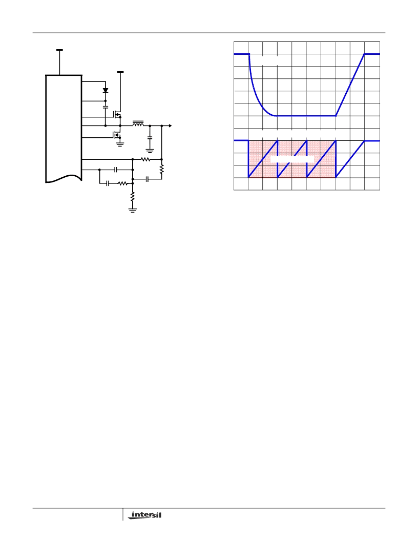
Figure 3 illustrates the protection feature responding to an
overcurrent event. At time t0, an overcurrent condition is
sensed across the upper MOSFET. As a result, the regulator
is quickly shutdown and the internal soft-start function begins
producing soft-start ramps. The delay interval seen by the
output is equivalent to three soft-start cycles. The fourth
internal soft-start cycle initiates a normal soft-start ramp of
the output, at time t1. The output is brought back into
regulation by time t2, as long as the overcurrent event has
cleared.
Had the cause of the overcurrent still been present after the
delay interval, the overcurrent condition would be sensed
and the regulator would be shut down again for another
delay interval of three soft-start cycles. The resulting hiccup
mode style of protection would continue to repeat
indefinitely.
The overcurrent function will trip at a peak inductor current
(I
PEAK)
determined by:
I
x R
r
DS ON
)
where I
OCSET
is the internal OCSET current source (20
μ
A
typical). The OC trip point varies mainly due to the MOSFET
r
DS(ON)
variations. To avoid overcurrent tripping in the
normal operating load range, find the R
OCSET
resistor from
the equation above with:
1. The maximum r
DS(ON)
at the highest junction
temperature.
2. The minimum I
OCSET
from the specification table.
3. Determine I
PEAK
for
where
I is the output inductor ripple current.
,
For an equation for the ripple current see the section under
component guidelines titled ‘Output Inductor Selection’.
A small ceramic capacitor should be placed in parallel with
R
OCSET
to smooth the voltage across
R
OCSET
in the
presence of switching noise on the input voltage.
Current Sinking
The ISL6526 incorporates a MOSFET shoot-through
protection method which allows a converter to sink current
as well as source current. Care should be exercised when
designing a converter with the ISL6526 when it is known that
the converter may sink current.
When the converter is sinking current, it is behaving as a
boost converter that is regulating its input voltage. This
means that the converter is boosting current into the input
rail of the regulator. If there is nowhere for this current to go,
FIGURE 2. OUTPUT VOLTAGE SELECTION
+
R1
C
OUT
+3.3V
V
OUT
R4
L
OUT
ISL6526
C4
Q1
FB
UGATE
VCC
BOOT
COMP
D1
R2
C2
C1
R3
C3
PHASE
LGATE
Q2
CPVOUT
VIN
FIGURE 3. OVERCURRENT PROTECTION RESPONSE
0V
TIME
V
OUT
(2.5V)
T1
T0
T2
INTERNAL SOFT-START FUNCTION
DELAY INTERVAL
I
PEAK
----------------------------------------------------
=
I
PEAK
I
OUT MAX
)
I
2
(
----------
)
+
>
ISL6526
相關(guān)PDF資料 |
PDF描述 |
|---|---|
| ISL6527AIRZ-T | Single Synchronous Buck Pulse-Width Modulation (PWM) Controller |
| ISL6527CR-T | Single Synchronous Buck Pulse-Width Modulation (PWM) Controller |
| ISL6527EVAL2 | Single Synchronous Buck Pulse-Width Modulation (PWM) Controller |
| ISL6527CRZ | Single Synchronous Buck Pulse-Width Modulation (PWM) Controller |
| ISL6527CRZ-T | Single Synchronous Buck Pulse-Width Modulation (PWM) Controller |
相關(guān)代理商/技術(shù)參數(shù) |
參數(shù)描述 |
|---|---|
| ISL6526IR | 功能描述:IC REG CTRLR BUCK PWM VM 16-QFN RoHS:否 類別:集成電路 (IC) >> PMIC - 穩(wěn)壓器 - DC DC 切換控制器 系列:- 標(biāo)準(zhǔn)包裝:4,000 系列:- PWM 型:電壓模式 輸出數(shù):1 頻率 - 最大:1.5MHz 占空比:66.7% 電源電壓:4.75 V ~ 5.25 V 降壓:是 升壓:無 回掃:無 反相:無 倍增器:無 除法器:無 Cuk:無 隔離:無 工作溫度:-40°C ~ 85°C 封裝/外殼:40-VFQFN 裸露焊盤 包裝:帶卷 (TR) |
| ISL6526IR-T | 功能描述:IC REG CTRLR BUCK PWM VM 16-QFN RoHS:否 類別:集成電路 (IC) >> PMIC - 穩(wěn)壓器 - DC DC 切換控制器 系列:- 標(biāo)準(zhǔn)包裝:4,000 系列:- PWM 型:電壓模式 輸出數(shù):1 頻率 - 最大:1.5MHz 占空比:66.7% 電源電壓:4.75 V ~ 5.25 V 降壓:是 升壓:無 回掃:無 反相:無 倍增器:無 除法器:無 Cuk:無 隔離:無 工作溫度:-40°C ~ 85°C 封裝/外殼:40-VFQFN 裸露焊盤 包裝:帶卷 (TR) |
| ISL6526IR-TR51 | 制造商:Intersil Corporation 功能描述: |
| ISL6526IR-TR5146 | 制造商:Rochester Electronics LLC 功能描述:- Bulk |
| ISL6526IR-TR5164 | 制造商:Intersil Corporation 功能描述: |
發(fā)布緊急采購(gòu),3分鐘左右您將得到回復(fù)。