- 您現(xiàn)在的位置:買賣IC網(wǎng) > Datasheet目錄38 > IRS2548DSPBF (International Rectifier)IC PFC Datasheet資料下載
參數(shù)資料
| 型號: | IRS2548DSPBF |
| 廠商: | International Rectifier |
| 文件頁數(shù): | 15/22頁 |
| 文件大小: | 320K |
| 描述: | IC PFC |
| 特色產(chǎn)品: | IRS2548D LED Driver |
| 標(biāo)準(zhǔn)包裝: | 55 |
| 系列: | * |

IRS2548D
www.irf.com
?2011 International Rectifier
15
II. PFC Section
Functional Description
In most LED drivers rated at more than a few Watts
high power factor high power factor (PC) is a
requirement. The driver needs to appear as a
resistive load to the AC input line voltage. The
degree to which the circuit matches a purely
resistive load is measured by the phase shift
between the input voltage and input current
harmonic distortion of the input current waveform.
The cosine of the phase angle between the input
voltage and input current is defined as the
displacement power factor and the amount of
harmonic distortion determines the distortion power
factor and total harmonic distortion (THD). The
overall power factor is the ratio between real and
apparent power and includes both displacement
and distortion. A power factor of 1.0 corresponds to
zero phase shift and a THD of 0% representing a
pure sinusoidal current waveform. In order to
provide a high PF and a low THD the IRS2548D
includes an active power factor correction (PFC)
circuit.
The control method implemented in the IRS2548D
is designed for a PFC Boost converter (Figure 4)
running in critical-conduction mode, the boundary
between continuous and discontinuous mode.
During the off period of each switching cycle of the
PFC MOSFET the circuit waits until the inductor
current falls to zero before turning the PFC
MOSFET on again. The PFC MOSFET is turned on
and off at a much higher frequency (>10KHz) than
the line input frequency (50 to 60Hz).
CBUS
+
(+)
(-)
MPFC
LPFC
DPFC
DC Bus
Figure 4: Boost converter circuit.
When the switch MPFC is turned on the inductor
LPFC is connected between the rectified line input
(+) and (-) causing the current in LPFC to rise
linearly. When MPFC is turned off LPFC is
connected between the rectified line input (+) and
the DC bus capacitor CBUS through diode DPFC
and the stored energy in LPFC supplies a current
into CBUS. MPFC is turned on and off at a high
frequency and the voltage on CBUS charges up to
a specified voltage. The feedback loop of the
IRS2548D regulates this voltage to a fixed value by
continuously monitoring the DC bus voltage and
adjusting the on-time of MPFC accordingly. For an
increasing DC bus the on-time is decreased and for a
decreasing DC bus the on-time is increased. This
negative feedback control is performed with a slow
loop speed such that the average inductor current
smoothly follows the low-frequency line input voltage
for high power factor and low THD. The on-time of
MPFC therefore appears to be fixed (except for on
time modulation which is discussed later) over
several cycles of the line voltage. With a fixed on-
time and an off-time determined by the inductor
current discharging to zero the switching frequency
and duty cycle vary to produce a high frequency near
the zero crossing of the AC input line voltage and a
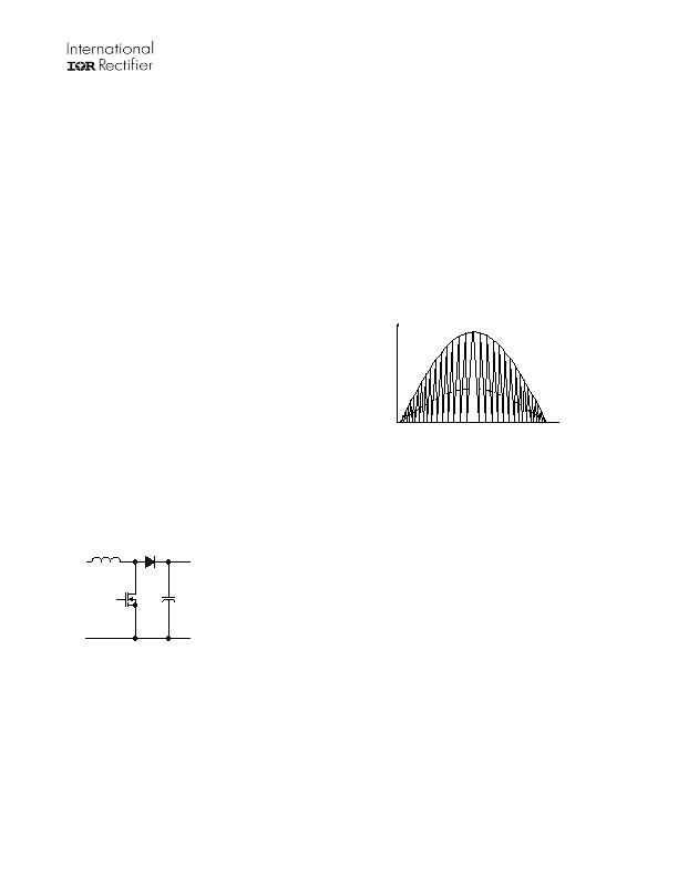
lower frequency at the peak (Figure 5).
V, I
t
Figure 5: Sinusoidal line input voltage (solid
line), triangular PFC Inductor current and
smoothed sinusoidal line input current
(dashed line) over one half-cycle of the AC line
input voltage.
When the line input voltage is low (near the zero
crossing), the inductor current will charge to a
lower peak level and therefore the discharge time
will be fast resulting in a high switching frequency.
When the input line voltage is high (near the
peak), the inductor current will charge up to a
higher amount and the discharge time will be
longer giving a lower switching frequency.
The PFC control circuit of the IRS2548D (Figure 6)
includes five control pins: VBUS, COMP, ZX, PFC
and OC. The VBUS pin measures the DC bus
voltage via an external resistor voltage divider.
The COMP pin voltage at the transconductance
error amplifier output sets the on-time of MPFC
where the speed of the feedback loop is
determined by the external COMP capacitor. The
ZX input detects when the inductor current has
discharged to zero each switching cycle using a
secondary winding from the PFC inductor. The
PFC output provides the gate driver output for the
external MOSFET, MPFC. The OC pin senses the
current flowing through MPFC and performs cycle-
by-cycle over-current protection.
相關(guān)PDF資料 |
PDF描述 |
|---|---|
| IRS2580DSPBF | IC PFC |
| ISL6111CR-T | IC CTRLR HOT PLUG SWITCH 20-QFN |
| ISL6112INZA-T | IC PWR CNTRLR DUAL SLT 48-TQFP |
| ISL6114IRZA | IC HOT PLUG CTRLR PCI-E 48-QFN |
| 4006-020 | LED CONST CURRENT RESISTOR 20MA |
相關(guān)代理商/技術(shù)參數(shù) |
參數(shù)描述 |
|---|---|
| IRS2548DSPBF | 制造商:International Rectifier 功能描述:IC LED DRVR SOIC |
| IRS2548DSTRPBF | 功能描述:LED照明驅(qū)動器 PFC + Hlf Brdg Combo LED Drvr IC RoHS:否 制造商:STMicroelectronics 輸入電壓:11.5 V to 23 V 工作頻率: 最大電源電流:1.7 mA 輸出電流: 最大工作溫度: 安裝風(fēng)格:SMD/SMT 封裝 / 箱體:SO-16N |
| IRS2552D | 制造商:未知廠家 制造商全稱:未知廠家 功能描述:CCFL/EEFL BALLAST CONTROLLER IC |
| IRS2552DPBF | 功能描述:功率驅(qū)動器IC CCFL / EEFL Ballast Cntrl IC RoHS:否 制造商:Micrel 產(chǎn)品:MOSFET Gate Drivers 類型:Low Cost High or Low Side MOSFET Driver 上升時間: 下降時間: 電源電壓-最大:30 V 電源電壓-最小:2.75 V 電源電流: 最大功率耗散: 最大工作溫度:+ 85 C 安裝風(fēng)格:SMD/SMT 封裝 / 箱體:SOIC-8 封裝:Tube |
| IRS2552DSPBF | 功能描述:功率驅(qū)動器IC CCFL / EEFL BALLAST 600V CTRL 300mA RoHS:否 制造商:Micrel 產(chǎn)品:MOSFET Gate Drivers 類型:Low Cost High or Low Side MOSFET Driver 上升時間: 下降時間: 電源電壓-最大:30 V 電源電壓-最小:2.75 V 電源電流: 最大功率耗散: 最大工作溫度:+ 85 C 安裝風(fēng)格:SMD/SMT 封裝 / 箱體:SOIC-8 封裝:Tube |
發(fā)布緊急采購,3分鐘左右您將得到回復(fù)。