- 您現(xiàn)在的位置:買賣IC網(wǎng) > PDF目錄360846 > IM04TS The Best Relaytion PDF資料下載
參數(shù)資料
| 型號: | IM04TS |
| 英文描述: | The Best Relaytion |
| 中文描述: | 最佳Relaytion |
| 文件頁數(shù): | 3/10頁 |
| 文件大小: | 610K |
| 代理商: | IM04TS |
3
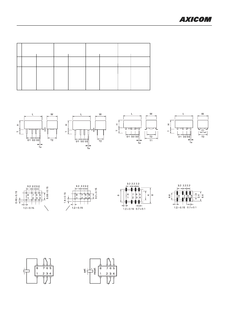
IM Relay
THT Version
Mounting hole layout
View onto the component side of the PCB
(top view)
Terminal assignment
Relay - top view
Non-latching type,
not energized condition
Dimensions
IM THT
Standard
mm
10
±
0.08 0.393
±
0.003 10
±
0.08
W 6
±
0.08
0.236
±
0.003 5.7
±
0.3
H
5.65 -0.2
0.222 -0.008 5.85 -0.15 0.230 -0.006 5.65 -0.2
T
3.2
0.125
3.2
T1 N/A
N/A
N/A
T2 5.08
±
0.1
0.200
±
0.004 3.2
±
0.1
D1 3.2
±
0.15 0.126
±
0.006 3.2
±
0.15 0.126
±
0.006 3.2
±
0.15
D2 2.2
±
0.15 0.087
±
0.006 2.2
±
0.15 0.087
±
0.006 2.2
±
0.15
Tw 0.4
0.015
0.4
S
0.3
±
0.05 0.011
±
0.002 0.3
±
0.05
IM THT
Narrow
mm
IM SMT
Gull Wings
mm
IM SMT
J-Legs
inch
inch
inch
L
0.393
±
0.003 10
±
0.08
0.224
±
0.012 6
±
0.08
0.393
±
0.003 10
±
0.08 0.393
±
0.003
0.236
±
0.003 6
±
0.08
0.222 -0.008 5.65 -0.2
N/A
N/A
0.295
±
0.011 2.8
±
0.2
0.200
±
0.004 5.08
±
0.1 0.200
±
0.004
0.126
±
0.006 3.2
±
0.15 0.126
±
0.006
0.087
±
0.006 2.2
±
0.15 0.087
±
0.006
0.015
0.4
N/A
N/A
0.236
±
0.003
0.222 -0.008
N/A
0.110
±
0.007
0.125
N/A
0.126
±
0.006 5.08
±
0.1
N/A
7.5
±
0.3
0.015
0.011
±
0.002 N/A
0.4
0.015
N/A
SMT Version
Gull Wings
J Legs
Solder pad layout
View onto the component side of the PCB
(top view)
Gull Wings
J Legs
min. 0.75
Latching type, 1 coil
reset condition
Standard version
Narrow version
Standard version
Narrow version
相關PDF資料 |
PDF描述 |
|---|---|
| IM05CGR | The Best Relaytion |
| IM05GR | The Best Relaytion |
| IM05JR | The Best Relaytion |
| IM05NS | The Best Relaytion |
| IM05TS | The Best Relaytion |
相關代理商/技術參數(shù) |
參數(shù)描述 |
|---|---|
| IM0505HD1W | 制造商:未知廠家 制造商全稱:未知廠家 功能描述:DC to DC Converter |
| IM0505HS1W | 制造商:未知廠家 制造商全稱:未知廠家 功能描述:DC to DC Converter |
| IM0509HD1W | 制造商:未知廠家 制造商全稱:未知廠家 功能描述:DC to DC Converter |
| IM0509HS1W | 制造商:未知廠家 制造商全稱:未知廠家 功能描述:DC to DC Converter |
| IM0512HD1W | 制造商:未知廠家 制造商全稱:未知廠家 功能描述:DC to DC Converter |
發(fā)布緊急采購,3分鐘左右您將得到回復。