- 您現(xiàn)在的位置:買(mǎi)賣(mài)IC網(wǎng) > PDF目錄4082 > IDT79RC32K438-233BBG (IDT, Integrated Device Technology Inc)IC MPU 32BIT CORE 233MHZ 416-BGA PDF資料下載
參數(shù)資料
| 型號(hào): | IDT79RC32K438-233BBG |
| 廠商: | IDT, Integrated Device Technology Inc |
| 文件頁(yè)數(shù): | 11/59頁(yè) |
| 文件大小: | 0K |
| 描述: | IC MPU 32BIT CORE 233MHZ 416-BGA |
| 標(biāo)準(zhǔn)包裝: | 40 |
| 系列: | Interprise™ |
| 處理器類(lèi)型: | MIPS32 32-位 |
| 速度: | 233MHz |
| 電壓: | 1.2V |
| 安裝類(lèi)型: | 表面貼裝 |
| 封裝/外殼: | 416-BGA |
| 供應(yīng)商設(shè)備封裝: | 416-PBGA(27x27) |
| 包裝: | 托盤(pán) |
| 其它名稱(chēng): | 79RC32K438-233BBG |
第1頁(yè)第2頁(yè)第3頁(yè)第4頁(yè)第5頁(yè)第6頁(yè)第7頁(yè)第8頁(yè)第9頁(yè)第10頁(yè)當(dāng)前第11頁(yè)第12頁(yè)第13頁(yè)第14頁(yè)第15頁(yè)第16頁(yè)第17頁(yè)第18頁(yè)第19頁(yè)第20頁(yè)第21頁(yè)第22頁(yè)第23頁(yè)第24頁(yè)第25頁(yè)第26頁(yè)第27頁(yè)第28頁(yè)第29頁(yè)第30頁(yè)第31頁(yè)第32頁(yè)第33頁(yè)第34頁(yè)第35頁(yè)第36頁(yè)第37頁(yè)第38頁(yè)第39頁(yè)第40頁(yè)第41頁(yè)第42頁(yè)第43頁(yè)第44頁(yè)第45頁(yè)第46頁(yè)第47頁(yè)第48頁(yè)第49頁(yè)第50頁(yè)第51頁(yè)第52頁(yè)第53頁(yè)第54頁(yè)第55頁(yè)第56頁(yè)第57頁(yè)第58頁(yè)第59頁(yè)
19 of 59
May 25, 2004
IDT 79RC32438
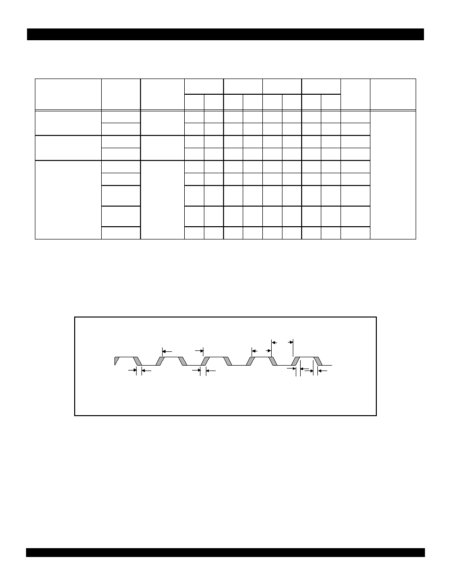
System Clock Parameters
Values based on systems running at recommended supply voltages and operating temperatures, as shown in Tables 15 and 16.
Figure 3 Clock Parameters Waveform
Parameter
Symbol
Reference
Edge
200MHz
233MHz
266MHz
300MHz
Units
Timing
Diagram
Reference
Min
Max
Min
Max
Min
Max
Min
Max
PCLK1
1. The CPU pipeline clock (PCLK) speed is selected during cold reset by the boot configuration vector (see Table 3).
Frequency
none
200
233
200
266
200
300
MHz
See Figure 3.
Tper
5.0
4.2
5.0
3.8
5.0
3.3
5.0
ns
ICLK2,3,4
2. ICLK is the internal IPBus clock. It is always equal to PCLK divided by 2. This clock cannot be sampled externally.
3. The ethernet clock (MIIxRXCLK and MIIxTXCLK) frequency must be equal to or less than 1/2 ICLK (MIIxRXCLK and MIIxTXCLK <= 1/2(ICLK)).
4. PCICLK must be equal to or less than two times ICLK (PCICLK <= 2(ICLK)) with a maximum PCICLK of 66MHz.
Frequency
none
100
116.5
100
133
100
150
MHz
Tper
10.0
8.5
10.0
7.5
6.7
10.0
ns
CLK5
5. The input clock (CLK) is input from the external oscillator to the internal PLL.
Frequency
none
25
66.6
25
77.6
25
88.6
25
100
MHz
Tper_5a
15.0
40.0
12.9
40.0
11.2
40.0
10
40
ns
Thigh_5a,
Tlow_5a
40
60
40
60
40
60
40
60
% of
Tper_5a
Trise_5a,
Tfall_5a
—3.0
ns
Tjitter_5a
—
0.1
—
0.1
—
0.1
—
0.1
ns
Table 5 Clock Parameters
Tlow_5a
Thigh_5a
Tper_5a
CLK
Trise_5a
Tfall_5a
Tjitter_5a
相關(guān)PDF資料 |
PDF描述 |
|---|---|
| IDT71V65603S100BQI | IC SRAM 9MBIT 100MHZ 165FBGA |
| IDT79RC32K438-233BB | IC MPU 32BIT CORE 233MHZ 416-BGA |
| IDT70V05L35J8 | IC SRAM 64KBIT 35NS 68PLCC |
| HFW20R-2STE1LF | CONN FPC/FFC 20POS 1MM R/A SMD |
| IDT70V05L25J8 | IC SRAM 64KBIT 25NS 68PLCC |
相關(guān)代理商/技術(shù)參數(shù) |
參數(shù)描述 |
|---|---|
| IDT79RC32K438-233BBGI | 功能描述:IC MPU 32BIT CORE 233MHZ 416-BGA RoHS:是 類(lèi)別:集成電路 (IC) >> 嵌入式 - 微處理器 系列:Interprise™ 標(biāo)準(zhǔn)包裝:40 系列:MPC83xx 處理器類(lèi)型:32-位 MPC83xx PowerQUICC II Pro 特點(diǎn):- 速度:267MHz 電壓:0.95 V ~ 1.05 V 安裝類(lèi)型:表面貼裝 封裝/外殼:516-BBGA 裸露焊盤(pán) 供應(yīng)商設(shè)備封裝:516-PBGAPGE(27x27) 包裝:托盤(pán) |
| IDT79RC32K438-233BBI | 功能描述:IC MPU 32BIT CORE 233MHZ 416-BGA RoHS:否 類(lèi)別:集成電路 (IC) >> 嵌入式 - 微處理器 系列:Interprise™ 標(biāo)準(zhǔn)包裝:40 系列:MPC83xx 處理器類(lèi)型:32-位 MPC83xx PowerQUICC II Pro 特點(diǎn):- 速度:267MHz 電壓:0.95 V ~ 1.05 V 安裝類(lèi)型:表面貼裝 封裝/外殼:516-BBGA 裸露焊盤(pán) 供應(yīng)商設(shè)備封裝:516-PBGAPGE(27x27) 包裝:托盤(pán) |
| IDT79RC32K438-266BB | 功能描述:IC MPU 32BIT CORE 266MHZ 416-BGA RoHS:否 類(lèi)別:集成電路 (IC) >> 嵌入式 - 微處理器 系列:Interprise™ 標(biāo)準(zhǔn)包裝:40 系列:MPC83xx 處理器類(lèi)型:32-位 MPC83xx PowerQUICC II Pro 特點(diǎn):- 速度:267MHz 電壓:0.95 V ~ 1.05 V 安裝類(lèi)型:表面貼裝 封裝/外殼:516-BBGA 裸露焊盤(pán) 供應(yīng)商設(shè)備封裝:516-PBGAPGE(27x27) 包裝:托盤(pán) |
| IDT79RC32K438-266BBG | 功能描述:IC MPU 32BIT CORE 266MHZ 416-BGA RoHS:是 類(lèi)別:集成電路 (IC) >> 嵌入式 - 微處理器 系列:Interprise™ 標(biāo)準(zhǔn)包裝:40 系列:MPC83xx 處理器類(lèi)型:32-位 MPC83xx PowerQUICC II Pro 特點(diǎn):- 速度:267MHz 電壓:0.95 V ~ 1.05 V 安裝類(lèi)型:表面貼裝 封裝/外殼:516-BBGA 裸露焊盤(pán) 供應(yīng)商設(shè)備封裝:516-PBGAPGE(27x27) 包裝:托盤(pán) |
| IDT79RC32K438-266BBGI | 功能描述:IC MPU 32BIT CORE 266MHZ 416-BGA RoHS:是 類(lèi)別:集成電路 (IC) >> 嵌入式 - 微處理器 系列:Interprise™ 標(biāo)準(zhǔn)包裝:40 系列:MPC83xx 處理器類(lèi)型:32-位 MPC83xx PowerQUICC II Pro 特點(diǎn):- 速度:267MHz 電壓:0.95 V ~ 1.05 V 安裝類(lèi)型:表面貼裝 封裝/外殼:516-BBGA 裸露焊盤(pán) 供應(yīng)商設(shè)備封裝:516-PBGAPGE(27x27) 包裝:托盤(pán) |
發(fā)布緊急采購(gòu),3分鐘左右您將得到回復(fù)。