- 您現在的位置:買賣IC網 > PDF目錄2078 > IDT74FCT810CTSOG8 (IDT, Integrated Device Technology Inc)IC CLK BUFFER 1:5 100MHZ 20-SOIC PDF資料下載
參數資料
| 型號: | IDT74FCT810CTSOG8 |
| 廠商: | IDT, Integrated Device Technology Inc |
| 文件頁數: | 2/6頁 |
| 文件大?。?/td> | 0K |
| 描述: | IC CLK BUFFER 1:5 100MHZ 20-SOIC |
| 標準包裝: | 1,000 |
| 系列: | 74FCT |
| 類型: | 扇出緩沖器(分配) |
| 電路數: | 2 |
| 比率 - 輸入:輸出: | 1:5 |
| 差分 - 輸入:輸出: | 無/無 |
| 輸入: | TTL |
| 輸出: | TTL |
| 頻率 - 最大: | 100MHz |
| 電源電壓: | 4.75 V ~ 5.25 V |
| 工作溫度: | 0°C ~ 70°C |
| 安裝類型: | 表面貼裝 |
| 封裝/外殼: | 20-SOIC(0.295",7.50mm 寬) |
| 供應商設備封裝: | 20-SOIC |
| 包裝: | 帶卷 (TR) |
| 其它名稱: | 74FCT810CTSOG8 |
2
COMMERCIALTEMPERATURERANGE
IDT74FCT810BT/CT
FASTCMOSBUFFER/CLOCKDRIVER
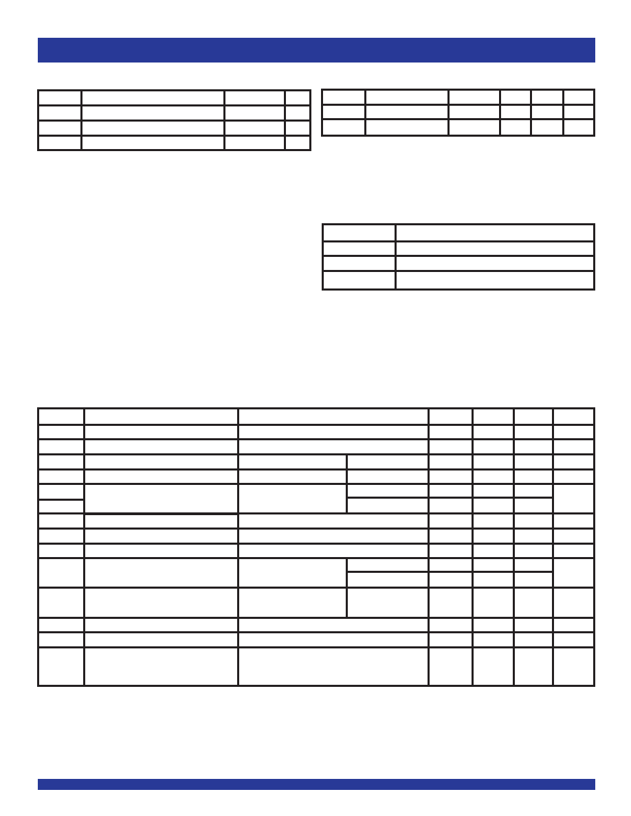
ABSOLUTE MAXIMUM RATINGS(1)
Symbol
Description
Max
Unit
VTERM
TerminalVoltagewithRespecttoGND
–0.5 to +7
V
TSTG
StorageTemperature
–65to+150
°C
IOUT
DCOutputCurrent
–60to+120
mA
NOTE:
1. Stresses greater than those listed under ABSOLUTE MAXIMUM RATINGS may cause
permanent damage to the device. This is a stress rating only and functional operation
of the device at these or any other conditions above those indicated in the operational
sections of this specification is not implied. Exposure to absolute maximum rating
conditions for extended periods may affect reliability.
PIN DESCRIPTION
Pin Names
Description
OEA
, OEB
3-StateOutput-EnableInputs(ActiveLOW)
INA, INB
Clock Inputs
OAx, OBx
ClockOutputs
CAPACITANCE (TA = +25OC, f = 1.0MHz)
Symbol
Parameter(1)
Conditions
Typ.
Max.
Unit
CIN
InputCapacitance
VIN = 0V
4.5
6
pF
COUT
OutputCapacitance
VOUT = 0V
5.5
8
pF
NOTE:
1. This parameter is measured at characterization but not tested.
DC ELECTRICAL CHARACTERISTICS OVER OPERATING RANGE
FollowingConditionsApplyUnlessOtherwiseSpecified:
Commercial: TA = 0°C to +70°C, VCC = 5V ± 5%
Symbol
Parameter
TestConditions(1)
Min.
Typ.(2)
Max.
Unit
VIH
Input HIGH Level (Input pins)
Guaranteed Logic HIGH Level
2
—
V
VIL
Input LOW Level
GuaranteedLogicLOWLevel
—
0.8
V
IIH
Input HIGH Current (Input pins)
VCC = Max.
VI = 2.7V
—
±1A
IIL
InputLOWCurrent(Inputpins)
VCC = Max.
VI = 0.5V
—
±1A
IOZH
HighImpedanceOutputCurrent
VCC = Max.
VO = 2.7V
—
±1A
IOZL
(3-StateOutputpins)
VO = 0.5V
—
±1
II
Input HIGH Current
VCC = Max., VI = VCC (Max.)
—
±1A
VIK
ClampDiodeVoltage
VCC = Min., IIN = –18mA
—
–0.7
–1.2
V
IOS
ShortCircuitCurrent
VCC = Max., VO = GND(3)
–60
–120
–225
mA
VOH
Output HIGH Voltage
VCC = Min.
IOH = –15mA
2.4
3.3
—
V
VIN = VIH or VIL
IOH = –32mA(4)
23
—
VOL
OutputLOWVoltage
VCC = Min.
IOL = 48mA
—
0.3
0.55
V
VIN = VIH or VIL
IOFF
Input/OutputPowerOffLeakage
VCC = 0V, VIN or VO
≤4.5V
—
±1A
VH
Input Hysteresis for all inputs
—
150
—
mV
ICCL
Quiescent Power Supply Current
VCC = Max., VIN = GND or VCC
—
5
500
A
ICCH
ICCZ
NOTES:
1. For conditions shown as Max. or Min., use appropriate value specified under Electrical Characteristics for the applicable device type.
2. Typical values are at Vcc = 5V, +25°C ambient.
3. Not more than one output should be shorted at one time. Duration of the test should not exceed one second.
4. Duration of the condition should not exceed one second.
相關PDF資料 |
PDF描述 |
|---|---|
| IDT74FST6800QG | IC BUS SWITCH 10BIT 24-QSOP |
| IDT74LVC162244APFG | IC BUFF DVR TRI-ST 16BIT 48TVSOP |
| IDT74LVC162245APFG | IC BUS TRSCVR 3-ST 16BIT 48TVSOP |
| IDT74LVC16244APFG | IC BUFF DVR TRI-ST 16BIT 48TVSOP |
| IDT74LVC16245APFG | IC BUS TRSCVR 3-ST 16BIT 48TVSOP |
相關代理商/技術參數 |
參數描述 |
|---|---|
| IDT74FCT821ATP | 制造商:Integrated Device Technology Inc 功能描述: |
| IDT74FCT821ATSO | 制造商:Integrated Device Technology Inc 功能描述: |
| IDT74FCT821BP | 制造商:Integrated Device Technology Inc 功能描述: |
| IDT74FCT821BTQ | 制造商:Rochester Electronics LLC 功能描述:- Bulk |
| IDT74FCT821CTQ | 制造商:Integrated Device Technology Inc 功能描述: 制造商:Integrated Device Technology Inc 功能描述:FCT SERIES, 10-BIT DRIVER, TRUE OUTPUT, PDSO24 |
發(fā)布緊急采購,3分鐘左右您將得到回復。