- 您現(xiàn)在的位置:買賣IC網(wǎng) > PDF目錄377191 > IDT54FCT521T (Integrated Device Technology, Inc.) FAST CMOS 8-BIT IDENTITY COMPARATOR PDF資料下載
參數(shù)資料
| 型號(hào): | IDT54FCT521T |
| 廠商: | Integrated Device Technology, Inc. |
| 英文描述: | FAST CMOS 8-BIT IDENTITY COMPARATOR |
| 中文描述: | 快速CMOS 8位身分比較器 |
| 文件頁數(shù): | 3/5頁 |
| 文件大小: | 100K |
| 代理商: | IDT54FCT521T |
IDT54/74FCT521T/AT/BT/CT
FAST CMOS 8-BIT IDENTITY COMPARATOR
MILITARY AND COMMERCIAL TEMPERATURE RANGES
6.16
3
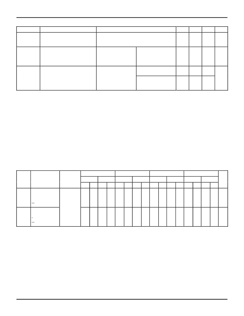
POWER SUPPLY CHARACTERISTICS
Symbol
Quiescent Power Supply
Current TTL
Inputs HIGH
I
CCD
Dynamic Power Supply Current
(4)
2572 tbl 06
Parameter
Test Conditions
(1)
Min.
Typ.
(2)
Max.
Unit
I
CC
V
CC
= Max.
V
IN
= 3.4V
(3)
—
0.5
2.0
mA
V
CC
= Max.
Outputs Open
One Input Toggling
50% Duty Cycle
V
CC
= Max.
Outputs Open
fi = 10MHz
One Bit Toggling
50% Duty Cycle
V
IN
= V
CC
V
IN
= GND
—
0.15
0.25
mA/
MHz
I
C
Total Power Supply Current
(5)
V
IN
= V
CC
V
IN
= GND
V
IN
= 3.4V
V
IN
= GND
—
1.5
3.5
mA
—
1.8
4.5
NOTES:
1. For conditions shown as Max. or Min., use appropriate value specified under Electrical Characteristics for the applicable device type.
2. Typical values are at V
CC
= 5.0V, +25
°
C ambient.
3. Per TTL driven input (V
IN
= 3.4V). All other inputs at V
CC
or GND.
4. This parameter is not directly testable, but is derived for use in Total Power Supply Calculations.
5. Values for these conditions are examples of the I
CC
formula. These limits are guaranteed but not tested.
6. I
C
= I
QUIESCENT
+ I
INPUTS
+ I
DYNAMIC
I
C
= I
CC
+
I
CC
D
H
N
T
+ I
CCD
(f
CP/
2 + f
i
N
i
)
I
CC
= Quiescent Current
I
CC
= Power Supply Current for a TTL High Input (V
IN
= 3.4V)
D
H
= Duty Cycle for TTL Inputs High
N
T
= Number of TTL Inputs at D
H
I
CCD
= Dynamic Current Caused by an Input Transition Pair (HLH or LHL)
f
CP
= Clock Frequency for Register Devices (Zero for Non-Register Devices)
f
i
= Input Frequency
N
i
= Number of Inputs at f
i
All currents are in milliamps and all frequencies are in megahertz.
SWITCHING CHARACTERISTICS OVER OPERATING RANGE
NOTES:
1. See test circuit and waveforms.
2. Minimum limits are guaranteed but not tested on Propagation Delays.
2572 tbl 07
IDT54/74FCT521T
IDT54/74FCT521AT
IDT54/74FCT521BT
IDT54/74FCT521CT
Com'l.
Mil.
Com'l.
Mil.
Com'l.
Mil.
Com'l.
Mil.
Symbol
t
PLH
t
PHL
Parameter
Propagation
Delay
An or Bn to
O
A
=
B
Propagation
Delay
I
A
=
B
to
O
A
=
B
Condition
(1)Min.
(2)
Max. Min.
(2)
Max. Min.
(2)
Max. Min.
(2)
Max. Min.
(2)
Max. Min.
(2)
Max. Min.
(2)
Max. Min.
(2)
Max.
Unit
CL = 50pF
RL = 500
1.5 11.0 1.5 15.0 1.5
7.2
1.5
9.5
1.5
5.5
1.5
7.3
1.5
4.5
1.5
5.1
ns
t
PLH
t
PHL
1.5 10.0 1.5
9.0
1.5
6.0
1.5
7.8
1.5
4.6
1.5
6.0
1.5
4.1
1.5
4.5
ns
相關(guān)PDF資料 |
PDF描述 |
|---|---|
| IDT54FCT521TD | FAST CMOS 8-BIT IDENTITY COMPARATOR |
| IDT54FCT521TDB | FAST CMOS 8-BIT IDENTITY COMPARATOR |
| IDT54FCT521TE | FAST CMOS 8-BIT IDENTITY COMPARATOR |
| IDT54FCT521TEB | FAST CMOS 8-BIT IDENTITY COMPARATOR |
| IDT74FCT521BTEB | FAST CMOS 8-BIT IDENTITY COMPARATOR |
相關(guān)代理商/技術(shù)參數(shù) |
參數(shù)描述 |
|---|---|
| IDT54FCT533DB | 制造商:Integrated Device Technology Inc 功能描述: |
| IDT54FCT543ADB | 制造商:MAJOR 功能描述: |
| IDT54FCT543ATDB | 制造商:MAJOR 功能描述: |
| IDT54FCT573ADB | 制造商:Integrated Device Technology Inc 功能描述: |
| IDT54FCT573ATDB | 制造商:Integrated Device Technology Inc 功能描述: 制造商:Integrated Device Technology Inc 功能描述:IC REGISTER OCTAL D 20CERDIP |
發(fā)布緊急采購,3分鐘左右您將得到回復(fù)。