- 您現(xiàn)在的位置:買賣IC網(wǎng) > PDF目錄385410 > HV7224X (SUPERTEX INC) 40-Channel Symmetric Row Driver PDF資料下載
參數(shù)資料
| 型號: | HV7224X |
| 廠商: | SUPERTEX INC |
| 元件分類: | 顯示驅(qū)動器 |
| 英文描述: | 40-Channel Symmetric Row Driver |
| 中文描述: | EL DISPLAY DRIVER, UUC55 |
| 封裝: | DIE |
| 文件頁數(shù): | 2/7頁 |
| 文件大小: | 466K |
| 代理商: | HV7224X |

2
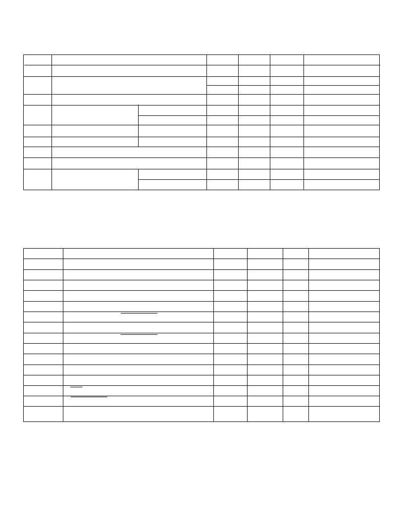
Symbol
Parameter
Min
Max
Units
Conditions
I
DD
I
PP
V
DD
supply current
High voltage supply current
10
mA
f
CLK
= 3MHz
Outputs low or High-Z
One Output High
1
All V
IN
= GND or V
DD
I
O
= -70mA
I
O
= -100
μ
A
I
O
= 70mA
I
O
= 100
μ
A
V
IH
= V
DD
V
IL
= 0V
2.0
4.0
100
mA
mA
μ
A
I
DDQ
V
OH
Quiescent V
DD
supply current
High-level output
HV
OUT
Data out
190
V
4.5
V
V
OL
Low-level output
HV
OUT
Data out
50
V
0.5
V
I
IH
I
IL
I
SAT
High-level logic input current
1.0
μ
A
Low-level logic input current
-1.0
μ
A
Saturation current HV
OUT
P-Ch
-80
mA
N-Ch
75
mA
Note:
1. Only one output can be turned on at a time.
Electrical Characteristics
(over recommended operating conditions of V
DD
= 5V, V
PP
= 240V, and T
A
= 25
°
C unless noted)
DC Characteristics
Symbol
Parameter
Min
Max
Units
Conditions
f
CLK
t
W (H/L)
t
SUD
t
HD
t
SUC
t
SUE
t
HC
t
HE
t
DHL*
t
DLH*
t
ONF
t
ONR
t
POW
t
OEW
Clock frequency
3.0
MHz
Pulse width - clock high or low
150
ns
Data set-up time before clock rises
50
ns
Data hold time after clock rises
50
ns
HV
OUT
delay from clock rises (Hi-Z to H or L)
HV
OUT
delay from Output Enable falls
HV
OUT
delay from clock rises (H or L to Hi-Z)
HV
OUT
delay from Output Enable rises
Delay time clock to data output falls
1.0
μ
s
C
L
= 330pF // R
L
= 10k
C
L
= 330pF // R
L
= 10k
C
L
= 330pF // R
L
= 10k
C
L
= 330pF // R
L
= 10k
C
L
= 15pF
C
L
= 15pF
C
L
= 330pF // R
L
= 10k
C
L
= 330pF // R
L
= 10k
600
ns
2.0
μ
s
600
ns
250
ns
Delay time clock to data output rises
250
ns
HV
OUT
fall time
HV
OUT
rise time
POL pulse width
2.0
μ
s
2.0
μ
s
3.0
μ
s
Output Enable pulse width
3.0
μ
s
Slew rate, V
PP
or GND
45
V/
μ
s
One active output driving
4.7nF load
AC Characteristics
* The delay is measured from the trailing edge of the clock but the data is triggered by the rising edge of the clock. There is an internal delay for the data output which is
equal to t
WH
. Therefore the delay is measured from the trailing edge of the clock.
HV7224
相關(guān)PDF資料 |
PDF描述 |
|---|---|
| HV8051 | High-Voltage EL Lamp Driver |
| HV8053 | High-Voltage EL Lamp Driver |
| HV9605C | High Voltage Current Mode PWM Controller |
| HV9605CNG | High Voltage Current Mode PWM Controller |
| HV9605CP | High Voltage Current Mode PWM Controller |
相關(guān)代理商/技術(shù)參數(shù) |
參數(shù)描述 |
|---|---|
| HV7225DG | 制造商:未知廠家 制造商全稱:未知廠家 功能描述:Interface IC |
| HV7225DJ | 制造商:未知廠家 制造商全稱:未知廠家 功能描述:Interface IC |
| HV7225PG | 制造商:未知廠家 制造商全稱:未知廠家 功能描述:Interface IC |
| HV7225PJ | 制造商:未知廠家 制造商全稱:未知廠家 功能描述:Interface IC |
| HV7225X | 制造商:未知廠家 制造商全稱:未知廠家 功能描述:Interface IC |
發(fā)布緊急采購,3分鐘左右您將得到回復(fù)。