- 您現(xiàn)在的位置:買賣IC網(wǎng) > PDF目錄384450 > HUFA76504DK8T (FAIRCHILD SEMICONDUCTOR CORP) 2.3A, 80V, 0.222 Ohm, Dual N-Channel, Logic Level UltraFET Power MOSFET PDF資料下載
參數(shù)資料
| 型號: | HUFA76504DK8T |
| 廠商: | FAIRCHILD SEMICONDUCTOR CORP |
| 元件分類: | 功率晶體管 |
| 英文描述: | 2.3A, 80V, 0.222 Ohm, Dual N-Channel, Logic Level UltraFET Power MOSFET |
| 中文描述: | 2500 mA, 80 V, 2 CHANNEL, N-CHANNEL, Si, SMALL SIGNAL, MOSFET, MS-012AA |
| 文件頁數(shù): | 1/13頁 |
| 文件大小: | 313K |
| 代理商: | HUFA76504DK8T |
2001 Fairchild Semiconductor Corporation
Rev. A, June 4, 2001
CAUTION: These devices are sensitive to electrostatic discharge; follow proper ESD Handling Procedures.
UltraFET is a registered trademark of Fairchild Corporation. PSPICE is a registered trademark of Cadence Corporation.
SABER is a
registered trademark
of Avanti corporation.
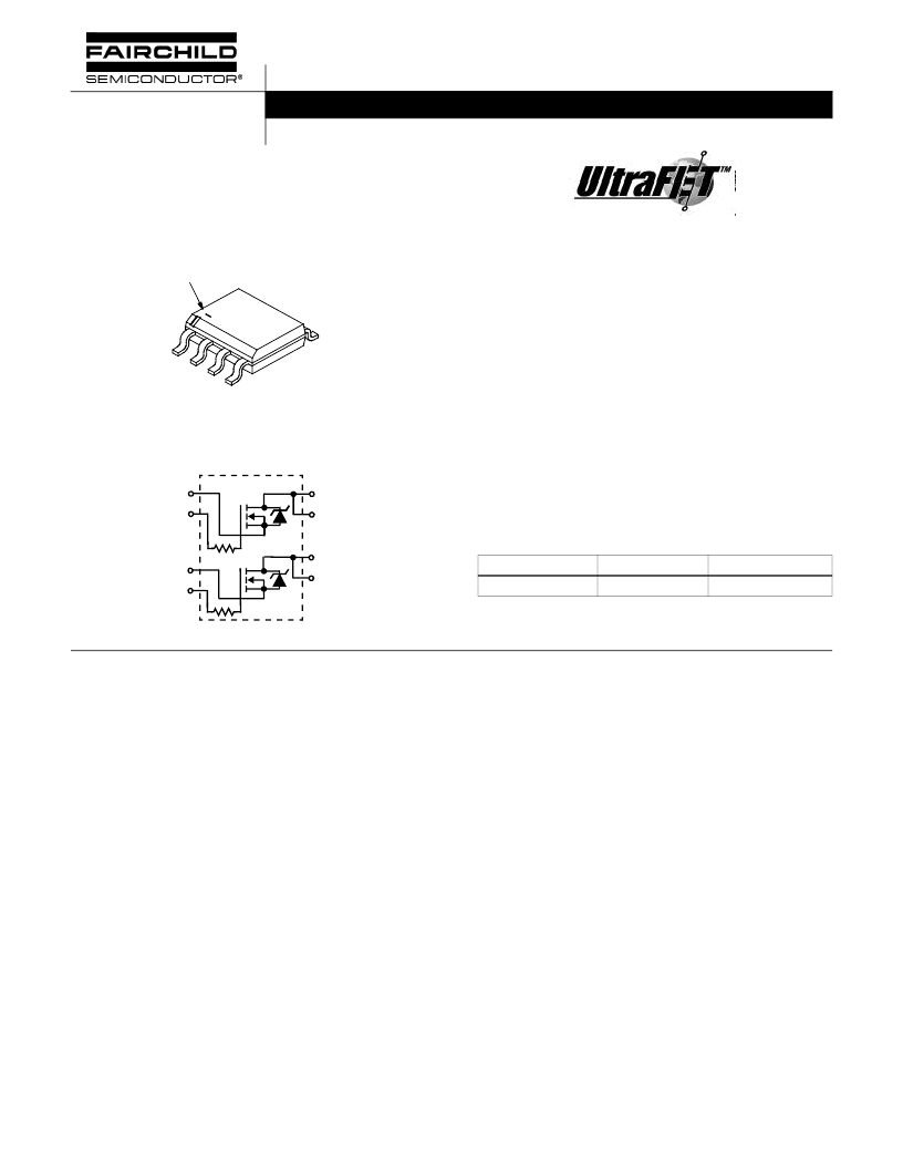
HUFA76504DK8
2.3A, 80V, 0.222 Ohm, Dual N-Channel,
Logic Level UltraFET Power MOSFET
Packaging
Symbol
Features
Ultra Low On-Resistance
- r
DS(ON)
= 0.200
,
V
GS
=
10V
- r
DS(ON)
= 0.222
,
V
GS
=
5V
Simulation Models
- Temperature Compensated PSPICE and SABER
Electrical Models
- Spice and SABER Thermal Impedance Models
- www.Fairchildsemi.com
Internal R
G
= 50
Peak Current vs Pulse Width Curve
UIS Rating Curve
Transient Thermal Impedance Curve vs Board Mounting
Area
Ordering Information
Absolute Maximum Ratings
T
A
= 25
o
C, Unless Otherwise Specified
This product has been designed to meet the extreme test conditions and environment demanded by the automotive industry. For a copy
of the requirements, see AEC Q101 at: http://www.aecouncil.com/
Reliability data can be found at: http://www.mtp.intersil.com/automotive.html.
All Fairchild semiconductor products are manufactured, assembled and tested under ISO9000 and QS9000 quality systems certification.
JEDEC MS-012AA
BRANDING DASH
1
2
3
4
5
DRAIN 1 (8)
SOURCE1 (1)
DRAIN 1 (7)
DRAIN 2 (6)
DRAIN 2 (5)
SOURCE2 (3)
GATE2 (4)
GATE1 (2)
PART NUMBER
PACKAGE
BRAND
HUFA76504DK8
MS-012AA
76504DK8
NOTE: When ordering, use the entire part number. Add the suffix T
to obtain the variant in tape and reel, e.g., HUFA76504DK8T.
HUFA76504DK8
80
80
±
16
UNITS
V
V
V
Drain to Source Voltage (Note 1). . . . . . . . . . . . . . . . . . . . . . . . . . . . . . . . . . . . . . . . . . V
DSS
Drain to Gate Voltage (R
GS
= 20k
) (Note 1). . . . . . . . . . . . . . . . . . . . . . . . . . . . . . . . V
DGR
Gate to Source Voltage . . . . . . . . . . . . . . . . . . . . . . . . . . . . . . . . . . . . . . . . . . . . . . . . . . V
GS
Drain Current
Continuous (T
A
= 25
o
C, V
GS
= 5V) (Note 2) . . . . . . . . . . . . . . . . . . . . . . . . . . . . . . . . . . I
D
Continuous (T
A
= 25
o
C, V
GS
= 10V) (Figure 2) (Note 2) . . . . . . . . . . . . . . . . . . . . . . . . . I
D
Continuous (T
A
= 100
o
C, V
GS
= 5V) (Note 3) . . . . . . . . . . . . . . . . . . . . . . . . . . . . . . . . . I
D
Continuous (T
A
= 100
o
C, V
GS
= 4.5V) (Figure 2) (Note 3). . . . . . . . . . . . . . . . . . . . . . . . I
D
Pulsed Drain Current . . . . . . . . . . . . . . . . . . . . . . . . . . . . . . . . . . . . . . . . . . . . . . . . . . .I
DM
Pulsed Avalanche Rating . . . . . . . . . . . . . . . . . . . . . . . . . . . . . . . . . . . . . . . . . . . . . . . . .UIS
Power Dissipation (Note 2) . . . . . . . . . . . . . . . . . . . . . . . . . . . . . . . . . . . . . . . . . . . . . . . . P
D
Derate Above 25
o
C . . . . . . . . . . . . . . . . . . . . . . . . . . . . . . . . . . . . . . . . . . . . . . . . . . . . . . .
Operating and Storage Temperature. . . . . . . . . . . . . . . . . . . . . . . . . . . . . . . . . . . . T
J
, T
STG
Maximum Temperature for Soldering
Leads at 0.063in (1.6mm) from Case for 10s. . . . . . . . . . . . . . . . . . . . . . . . . . . . . . . . . .T
L
Package Body for 10s, See Techbrief TB334 . . . . . . . . . . . . . . . . . . . . . . . . . . . . . . . T
pkg
NOTES:
1. T
J
= 25
o
C to 125
o
C.
2. 50
o
C/W measured using FR-4 board with 0.76 in
2
(490.3 mm
2
) copper pad at 1 second.
3. 228
o
C/W measured using FR-4 board with 0.006 in
2
(3.87 mm
2
) copper pad at 1000 seconds.
CAUTION:
Stresses above those listed in “Absolute Maximum Ratings” may cause permanent damage to the device. This is a stress only rating and operation of the
device at these or any other conditions above those indicated in the operational sections of this specification is not implied.
2.3
2.5
1.1
1.1
Figure 4
A
A
A
A
Figures 6, 17, 18
2.5
20
-55 to 150
W
mW/
o
C
o
C
300
260
o
C
o
C
Data Sheet
June 2001
[ /Title
(HUF7
6400S
K8)
/Sub-
ject
(60V,
0.072
Ohm,
4A, N-
Chan-
nel,
Logic
Level
UltraFE
Power
MOS-
FET)
/Author
/Key-
words
(Harris
Semi-
conduc-
tor, N-
Chan-
nel,
Logic
Level
UltraFE
Power
MOS-
相關(guān)PDF資料 |
PDF描述 |
|---|---|
| HUFA76504DK8 | 2.3A, 80V, 0.222 Ohm, Dual N-Channel, Logic Level UltraFET Power MOSFET |
| HUFA76609D3 | 10A, 100V, 0.165 Ohm, N-Channel, Logic Level UltraFET Power MOSFET |
| HUFA76609D3S | 10A, 100V, 0.165 Ohm, N-Channel, Logic Level UltraFET Power MOSFET |
| HUFA76619D3 | 18A, 100V, 0.087 Ohm, N-Channel, Logic Level UltraFET Power MOSFET |
| HUFA76619D3S | 18A, 100V, 0.087 Ohm, N-Channel, Logic Level UltraFET Power MOSFET |
相關(guān)代理商/技術(shù)參數(shù) |
參數(shù)描述 |
|---|---|
| HUFA76609D3 | 功能描述:MOSFET 10a 100V 0.165 Ohm Logic Level N-Ch RoHS:否 制造商:STMicroelectronics 晶體管極性:N-Channel 汲極/源極擊穿電壓:650 V 閘/源擊穿電壓:25 V 漏極連續(xù)電流:130 A 電阻汲極/源極 RDS(導(dǎo)通):0.014 Ohms 配置:Single 最大工作溫度: 安裝風(fēng)格:Through Hole 封裝 / 箱體:Max247 封裝:Tube |
| HUFA76609D3S | 功能描述:MOSFET 10a 100V 0.165 Ohm Logic Level N-Ch RoHS:否 制造商:STMicroelectronics 晶體管極性:N-Channel 汲極/源極擊穿電壓:650 V 閘/源擊穿電壓:25 V 漏極連續(xù)電流:130 A 電阻汲極/源極 RDS(導(dǎo)通):0.014 Ohms 配置:Single 最大工作溫度: 安裝風(fēng)格:Through Hole 封裝 / 箱體:Max247 封裝:Tube |
| HUFA76609D3ST | 功能描述:MOSFET 10a 100V 0.165 Ohm Logic Level N-Ch RoHS:否 制造商:STMicroelectronics 晶體管極性:N-Channel 汲極/源極擊穿電壓:650 V 閘/源擊穿電壓:25 V 漏極連續(xù)電流:130 A 電阻汲極/源極 RDS(導(dǎo)通):0.014 Ohms 配置:Single 最大工作溫度: 安裝風(fēng)格:Through Hole 封裝 / 箱體:Max247 封裝:Tube |
| HUFA76609D3ST_F085 | 功能描述:MOSFET Trans N-CH 100V 10A RoHS:否 制造商:STMicroelectronics 晶體管極性:N-Channel 汲極/源極擊穿電壓:650 V 閘/源擊穿電壓:25 V 漏極連續(xù)電流:130 A 電阻汲極/源極 RDS(導(dǎo)通):0.014 Ohms 配置:Single 最大工作溫度: 安裝風(fēng)格:Through Hole 封裝 / 箱體:Max247 封裝:Tube |
| HUFA76609D3ST_NL | 制造商:Rochester Electronics LLC 功能描述:- Bulk |
發(fā)布緊急采購,3分鐘左右您將得到回復(fù)。