- 您現(xiàn)在的位置:買賣IC網(wǎng) > PDF目錄385405 > HT8955A (Holtek Semiconductor Inc.) Voice Echo PDF資料下載
參數(shù)資料
| 型號: | HT8955A |
| 廠商: | Holtek Semiconductor Inc. |
| 英文描述: | Voice Echo |
| 中文描述: | 語音回聲 |
| 文件頁數(shù): | 4/7頁 |
| 文件大小: | 589K |
| 代理商: | HT8955A |

Symbol
Parameter
Test Conditions
Min.
Typ.
Max.
Unit
V
DD
Conditions
V
IH
“H” Input Voltage
—
—
0.7V
DD
—
V
DD
V
V
OMAX
Maximum Output Voltage
5V
R
L
>470k
1
1.5
—
V
Td
Maximum Delay Time
5V
SE L=open, 25kHz
sampling rate
0.15
0.2
—
s
Td
5V
SE L=VSS, 25kHz
sampling rate
0.6
0.8
—
s
S/N
Signal to Noise Ratio
5V
V
O
=1V, 400Hz
BW=10kHz
—
55
—
dB
THD
Total Harmonic Distortion
5V
V
O
=1V, 400Hz
BW=7kHz
—
0.5
—
%
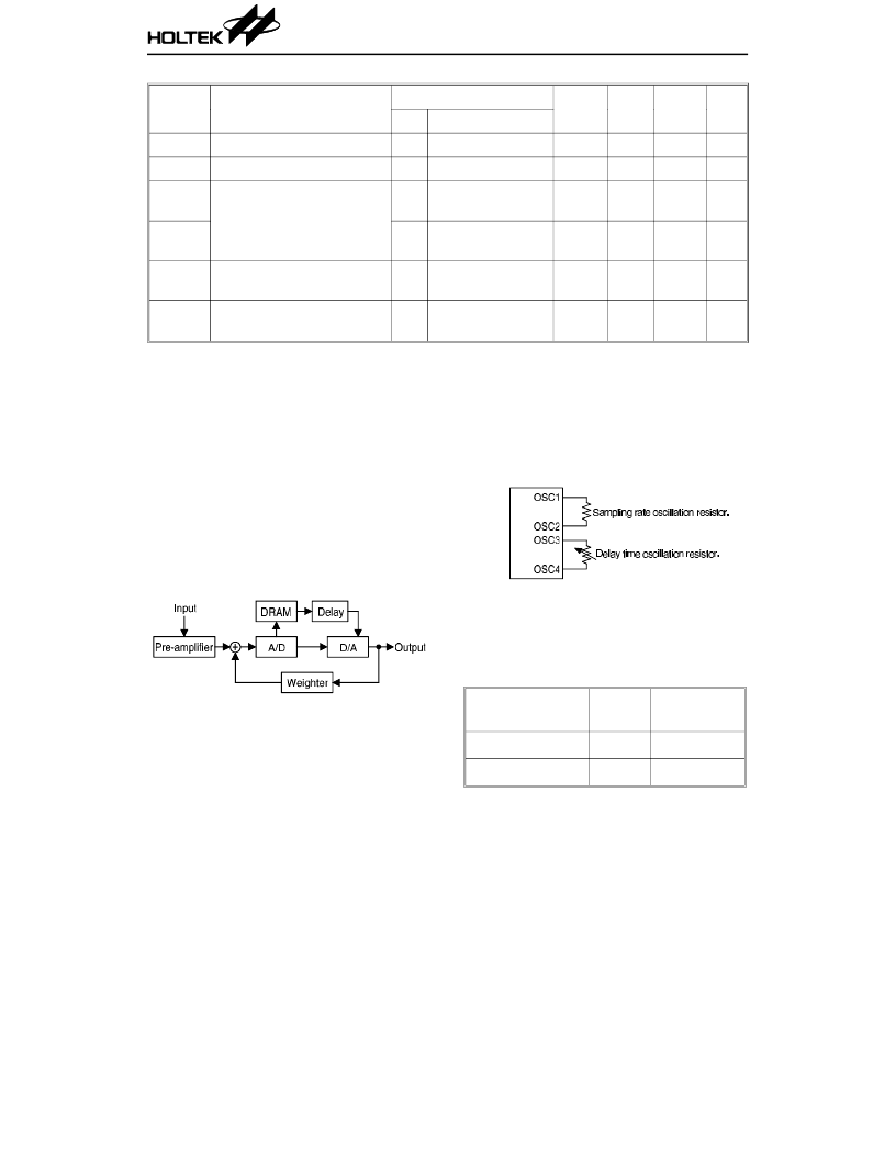
Functional Description
The HT8955A is a single chip LSI with an exter-
nal DRAM. It is designed for processing audio
signal delay. The chip includes a built-in pre-
amplifier, 10-bit A/D and D/A converters. The
A/D and D/A converters ensure low distortion as
well as high S/N ratio of the audio delay system.
The chip also provides two sets of oscillation
circuit for system sampling rate and audio echo
delay time.
Playing function block diagram
System oscillator
The HT8955A provides two oscillators, one for
the sampling rate and one for echo delay time.
The sampling rate oscillator requires an exter-
nal resistor between the OSC1 and OSC2 pins.
A higher sampling rate (25~50kHz) can thus be
derived by adjusting the oscillation resistor
without having a sophisticated low pass filter.
The delay time oscillator, on the other hand,
demands an external resistor between the
OSC3 and OSC4 pins. By altering the oscilla-
tion resistor, its delay time can be continuously
adjusted up to 0.8/0.2 seconds at a 25kHz sam-
pling rate for DRAM of 256K b/64K b.
DRAM selection
The HT8955A can interface with a DRAM for
storing delay signals. The type along with the
maximum delay time of DRAM is determined
by the status of the SE L pin as shown:
SE L Connection
DR AM
Type
Delay Time
VDD or Open
64K b
0.2 seconds
VSS
256Kb
0.8 seconds
HT8955A
4
5th May ’98
相關(guān)PDF資料 |
PDF描述 |
|---|---|
| HT8970 | Voice Echo |
| HT9011 | FM IF Detector |
| HT9015 | RF Single Chip for Cordless Phone |
| HT9020B | Call Progress Tone Detector |
| HT9020 | Call Progress Tone Decoder & ABR Controller |
相關(guān)代理商/技術(shù)參數(shù) |
參數(shù)描述 |
|---|---|
| HT8960 | 制造商:未知廠家 制造商全稱:未知廠家 功能描述:Consumer IC |
| HT8970 | 制造商:HOLTEK 制造商全稱:Holtek Semiconductor Inc 功能描述:Voice Echo |
| HT8970(16DIP) | 制造商:未知廠家 制造商全稱:未知廠家 功能描述:Consumer IC |
| HT8970(16SOP) | 制造商:未知廠家 制造商全稱:未知廠家 功能描述:Consumer IC |
| HT8972 | 制造商:HOLTEK 制造商全稱:Holtek Semiconductor Inc 功能描述:Voice Echo |
發(fā)布緊急采購,3分鐘左右您將得到回復(fù)。