- 您現(xiàn)在的位置:買賣IC網(wǎng) > PDF目錄370715 > HT817D0(20SOP) Speech Synthesizer PDF資料下載
參數(shù)資料
| 型號: | HT817D0(20SOP) |
| 英文描述: | Speech Synthesizer |
| 中文描述: | 語音合成器 |
| 文件頁數(shù): | 10/15頁 |
| 文件大小: | 207K |
| 代理商: | HT817D0(20SOP) |
HT817D0
10
March 15, 2000
In addition to the above-stated output sig-
nals, FLAG1 can also generate one of the fol-
lowing signals by code option:
Voice indicator output
FLAG1 is active low when voices are play-
ing. FLAG1 is also turned low when a voice
section is output. The brightness of FLAG1
varies with the volume. FLAG1 becomes
floating after the silence section is output or
the voice output is terminated.
End-pulse output
When the voice output is completed, the
FLAG1 pin outputs an active low pulse. The
pulse width can be programmed depending
on the customer s requirements.
The FLAG1 as well as FLAG2 pins are both
floating outputs when the chip is in the
standby state.
Volume control
The function of volume control can be set by
mask option. A code is written in the function
table for the purpose of controlling the volume
of each section output after the volume control
function is chosen. There are two volume op-
tions, namely, full range and half range.
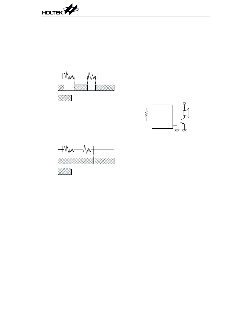
AUD
The AUD pin is a PMOS open drain structure.
It outputs voice signals to drive a speaker
through an external NPN transistor when the
chip is active. The AUD pin becomes a floating
output when the chip is in the standby state.
The 8050 type transistor with h
FE
150 is rec-
ommended for an output driver.
: & ) ( !
: & ) ( !
,
7
Powered by ICminer.com Electronic-Library Service CopyRight 2003
相關(guān)PDF資料 |
PDF描述 |
|---|---|
| HT817D0(24DIP) | Speech Synthesizer |
| HT817D0(24SOP) | Speech Synthesizer |
| HT817D0 | 16.8-Second LOG-PCM Speech |
| HT818D0(20DIP) | Speech Synthesizer |
| HT818D0(20SOP) | Speech Synthesizer |
相關(guān)代理商/技術(shù)參數(shù) |
參數(shù)描述 |
|---|---|
| HT818D0 | 制造商:HOLTEK 制造商全稱:Holtek Semiconductor Inc 功能描述:22.4-Second LOG-PCM Speech |
| HT818D0(20DIP) | 制造商:未知廠家 制造商全稱:未知廠家 功能描述:Speech Synthesizer |
| HT818D0(20SOP) | 制造商:未知廠家 制造商全稱:未知廠家 功能描述:Speech Synthesizer |
| HT818D0(24DIP) | 制造商:未知廠家 制造商全稱:未知廠家 功能描述:Speech Synthesizer |
| HT818D0(24SOP) | 制造商:未知廠家 制造商全稱:未知廠家 功能描述:Speech Synthesizer |
發(fā)布緊急采購,3分鐘左右您將得到回復(fù)。