- 您現(xiàn)在的位置:買賣IC網(wǎng) > PDF目錄384435 > HM9270C (ELAN Microelctronics Corp .) DTMF Receiver(集成了濾波器和數(shù)字譯碼器功能的雙音多頻(DTMF)接收器) PDF資料下載
參數(shù)資料
| 型號(hào): | HM9270C |
| 廠商: | ELAN Microelctronics Corp . |
| 英文描述: | DTMF Receiver(集成了濾波器和數(shù)字譯碼器功能的雙音多頻(DTMF)接收器) |
| 中文描述: | 雙音多頻接收器(集成了濾波器和數(shù)字譯碼器功能的雙音多頻(DTMF)的接收器) |
| 文件頁數(shù): | 7/10頁 |
| 文件大小: | 57K |
| 代理商: | HM9270C |
DTMF RECEIVER
HM 9270C/D
— 7 —
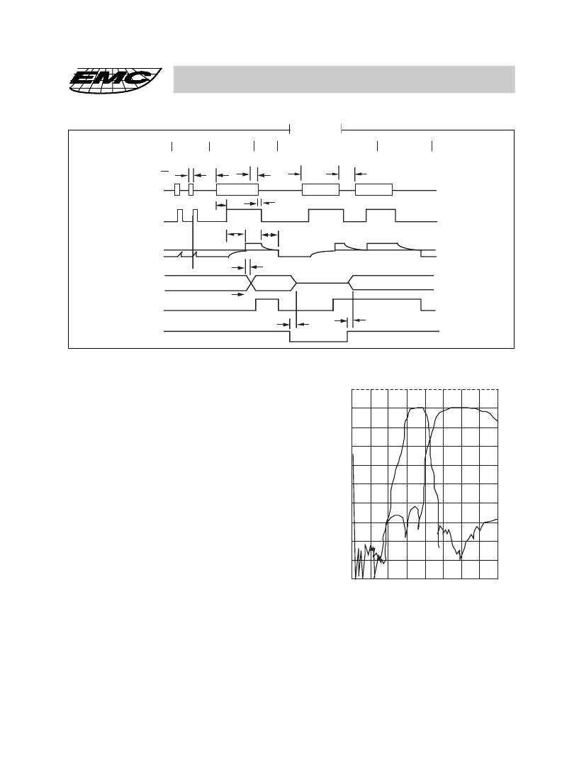
FIGURE 5. TIMING DIAGRAM
A. Short tone bursts: detected. Tone duration is invalid.
B. Tone #n is detected. Tone duration is valid. Decoded
to outputs.
C. End of tone #n is dectected and validated.
D. 3 State outputs disabled (high impedance).
E. Tone #n + 1 is detected. Tone duration is valid. De
coded to outputs.
F. Tristate outputs are enabled. Acceptable drop out of
tone #n + 1 does not negister at outputs.
G. End of tone #n + 1 is detected and validated.
FIGURE 5. TIMING DIAGRAM
the GT output is activated and drives V
to V
. GT continues to drive high as long as ESt remains high.
Finally after a short delay to allow the output latch to settle, the “delayed-steering” output flag, StD, goes
high, signaling that a recieved tone-pair has been registered. The contents of the output lacth are made
available on the 4-bit output bus by raising the 3-state control input (TOE) to a logic high. The steering
circuit works in reverse to validate the interdigit paues between signals. Thus, as well as rejecting signals
too short to be considered valid, the receiver will tolerate signal interruptions (“drop-out”) too short to be
considered a valid pause. The facility, together with the capability of selecting the steering time-constants
externally, allows the designer to tailor performance to meet a wide variety of system requiremetns.
FIGURE 6. TYPICAL FILTER
CHARACTERISTIC
Before registration of a decoded tone-pair, the receiver
checks for a valid signal duration (referred to as “charac-
ter-recognition-condition”). This check is per-
formed by an external RC time-constant driven by ESt.
A logic high on ESt causes V
(see Fig. 5) to rise as the
capacitor discharges. Provided signal-condition is
maintained (ESt remains high) for the validation period
(t
), Vc reaches the threshold (V
) of the steering logic
to register the tone-pair, latching its corresponding 4-bit
code (see Fig. 3) into the output latch. At this point,
STEERING CIRCUIT
D
A
B
C
E
F
G
t
REC
t
REC
INTERDIGIT
PAUSE
t
ID
TONE DROPOUT
t
DO
TONE # n
TONE #n+1
TONE#n+1
t
DP
DA
t
GTP
t
PQ
t
t
GTA
V
Tst
DECODE TONE n-1
DECODED
TONE#n
t
PS
t
D
DECODED TONE # n + 1
HIGH
IMPEDANCE
t
PTE
PTD
t
EVENTS
ESt
DATA
OUTPUTS
Q1-Q4
TOE
St/GT
StD
OUTPUT
0
10
20
30
40
50
60
70
80
0
1K
2K
相關(guān)PDF資料 |
PDF描述 |
|---|---|
| HM9270D | DTMF RECEIVER |
| HMA2701R1 | FULL PITCH MINI-FLAT PACKAGE 4-PIN OPTOCOUPLERS |
| HMA121AR2V | FULL PITCH MINI-FLAT PACKAGE 4-PIN OPTOCOUPLERS |
| HMAA2705R4V | FULL PITCH MINI-FLAT PACKAGE 4-PIN OPTOCOUPLERS |
| HMAA2705V | FULL PITCH MINI-FLAT PACKAGE 4-PIN OPTOCOUPLERS |
相關(guān)代理商/技術(shù)參數(shù) |
參數(shù)描述 |
|---|---|
| HM9270D | 制造商:EMC 制造商全稱:ELAN Microelectronics Corp 功能描述:DTMF RECEIVER |
| HM92M | 制造商:HSMC 制造商全稱:HSMC 功能描述:PNP EPITAXIAL PLANAR TRANSISTOR |
| HM94 | 制造商:HSMC 制造商全稱:HSMC 功能描述:PNP EPITAXIAL PLANAR TRANSISTOR |
| HM965 | 制造商:HSMC 制造商全稱:HSMC 功能描述:NPN EPITAXIAL PLANAR TRANSISTOR |
| HM9-6516BB6129 | 制造商:Rochester Electronics LLC 功能描述:- Bulk |
發(fā)布緊急采購,3分鐘左右您將得到回復(fù)。