- 您現(xiàn)在的位置:買賣IC網(wǎng) > PDF目錄296185 > HLMP-Q106-R0031 (AGILENT TECHNOLOGIES INC) T-3/4 SINGLE COLOR LED, DEEP RED, 1.78 mm PDF資料下載
參數(shù)資料
| 型號: | HLMP-Q106-R0031 |
| 廠商: | AGILENT TECHNOLOGIES INC |
| 元件分類: | LED |
| 英文描述: | T-3/4 SINGLE COLOR LED, DEEP RED, 1.78 mm |
| 文件頁數(shù): | 7/12頁 |
| 文件大小: | 595K |
| 代理商: | HLMP-Q106-R0031 |
4
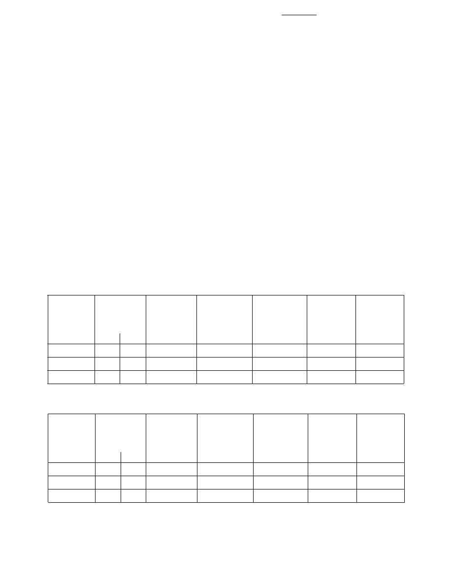
Optical Characteristics at TA= 25°C
Part
Luminous
Color,
Viewing
Number
Intensity
Total Flux
Peak
Dominant
Angle
Luminous
(Low
IV (mcd)
φ
V (mlm)
Wavelength
2
θ1/2
Efficacy
Current)
@ 0.5 mA[1]
@ 0.5 mA[2]
λ
peak (nm)
λ
d
[3] (nm)
Degrees[4]
η
v
[5]
HLMP-
Min.
Typ.
(lm/w)
Q156-H00xx
2.5
7
10.5
654
644
15
85
Q152-G00xx
1.6
2
-
654
644
35
85
P156-EG0xx
0.63
2
10.5
654
644
75
85
Notes:
1. The luminous intensity, Iv, is measured at the mechanical axis of the lamp package. The actual peak of the spatial radiation pattern
may not be aligned with this axis.
2.
φ
v is the total luminous flux output as measured with an integrating sphere.
3. The dominant wavelength,
λ
d, is derived from the CIE Chromaticity Diagram and represents the color of the device.
4.
θ1/2 is the off-axis angle where the liminous intensity is 1/2 the peak intensity.
5. Radiant intensity, Iv, in watts/steradian, may be calculated from the equation Iv= Iv/ηv, where Ivis the luminous intensity in candelas
and
η
v is the luminous efficacy in lumens/watt.
Optical Characteristics at TA= 25°C
Luminous
Color,
Viewing
Intensity
Total Flux
Peak
Dominant
Angle
Luminous
Part
IV (mcd)
φ
V (mlm)
Wavelength
2
θ1/2
Efficacy
Number
@ 20 mA[1]
@ 20 mA[2]
λ
peak (nm)
λ
d
[3] (nm)
Degrees[4]
η
v
[5]
HLMP-
Min.
Typ.
(lm/w)
Q106-R00xx
100
400
280
654
644
15
85
Q102-N00xx
25
100
-
654
644
35
85
P106-Q00xx
63
130
280
654
644
75
85
Absolute Maximum Ratings at TA = 25°C
Peak Forward Current[2] .......................................................... 300 mA
Average Forward Current (@ IPEAK = 300 mA)[1,2] .................... 30 mA
DC Forward Current[3] ............................................................... 50 mA
Power Dissipation .................................................................... 100 mW
Reverse Voltage (IR = 100 A) ......................................................... 5 V
Transient Forward Current (10
s Pulse)[4] ............................ 500 mA
Operating Temperature Range ...................................... -55 to +100
°C
Storage Temperature Range .......................................... -55 to +100
°C
LED Junction Temperature ....................................................... 110
°C
Lead Soldering Temperature
[1.6 mm (0.063 in.) from body ............................ 260
°C for 5 seconds
Reflow Soldering Temperatures
Convective IR ..................... 235
°C Peak, above 183°C for 90 seconds
VaporPhase ........................................................ 215
°C for 3 minutes
Notes:
1. Maximum IAVG at f = 1 kHz, DF = 10%.
2. Refer to Figure 7 to establish pulsed operating conditions.
3. Derate linearly as shown in Figure 6.
4. The transient peak current is the maximum non-recurring peak current the device
can withstand without damaging the LED die and wire bonds. It is not
recommended that the device be operated at peak currents above the Absolute
MaximumPeakForwardCurrent.
相關(guān)PDF資料 |
PDF描述 |
|---|---|
| HLMP-Q152-G0000 | T-3/4 SINGLE COLOR LED, DEEP RED, 1.78 mm |
| HLMP-Q405-H0010 | T-3/4 SINGLE COLOR LED, ORANGE, 1.78 mm |
| HLMP-S301-C0002 | SINGLE COLOR LED, YELLOW, 5 mm |
| HLMP-S301-B0000 | SINGLE COLOR LED, YELLOW, 5 mm |
| HM13-05003 | 1 ELEMENT, 500 uH, POWDERED IRON-CORE, GENERAL PURPOSE INDUCTOR |
相關(guān)代理商/技術(shù)參數(shù) |
參數(shù)描述 |
|---|---|
| HLMP-Q106-R0034 | 制造商:Avago Technologies 功能描述:POLY,DOME,TS ALGAAS,Z,T/R - Tape and Reel |
| HLMP-Q106-TU011 | 功能描述:標準LED-SMD Poly Dome Red RoHS:否 制造商:Vishay Semiconductors 封裝 / 箱體:0402 LED 大小:1 mm x 0.5 mm x 0.35 mm 照明顏色:Red 波長/色溫:631 nm 透鏡顏色/類型:Water Clear 正向電流:30 mA 正向電壓:2 V 光強度:54 mcd 顯示角:130 deg 系列:VLMx1500 封裝:Reel |
| HLMP-Q150 | 功能描述:標準LED-通孔 Poly Dome Red RoHS:否 制造商:Vishay Semiconductors 照明顏色:Red 光強度:0.7 mcd 波長/色溫:615 nm 顯示角:45 deg 透鏡顏色/類型:Clear, Non-Diffused 正向電流:70 mA 正向電壓:1.83 V to 3.03 V LED 大小:2 mm 系列: 封裝:Tube |
| HLMP-Q150#011 | 制造商:Hewlett Packard Co 功能描述:Manufacturer Supplied Status Information |
| HLMP-Q150 | 制造商:Avago Technologies 功能描述:LED SUBMIN RED |
發(fā)布緊急采購,3分鐘左右您將得到回復。