- 您現(xiàn)在的位置:買賣IC網(wǎng) > PDF目錄367204 > HLMP-6300 Subminiature LED Lamps PDF資料下載
參數(shù)資料
| 型號: | HLMP-6300 |
| 英文描述: | Subminiature LED Lamps |
| 中文描述: | 微型發(fā)光二極管 |
| 文件頁數(shù): | 10/14頁 |
| 文件大小: | 240K |
| 代理商: | HLMP-6300 |
1-183
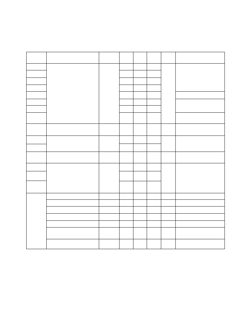
High Performance Green
Device
HLMP-
P502
P505
6500
6505
7040
Luminous Intensity
[1]
6800
6820
6853 to
6858
All
Forward Voltage
(Nonresistor Lamps)
6800
Forward Current
6820
(Resistor Lamps)
All
Reverse Breakdown
Voltage
P505
Parameter
Symbol
Min.
1.0
1.0
1.0
4.2
0.4
1.6
0.8
1.0
Typ.
3.0
5.0
7.0
20.0
0.6
5.0
2.0
3.0
Max.
Units
Test Conditions
I
F
= 10 mA
I
v
mcd
I
F
= 2 mA
V
F
= 5.0 Volts
I
F
= 10 mA
V
F
2.1
2.7
V
I
F
= 10 mA
9.6
13.0
I
F
mA
V
F
= 5.0 V
3.5
50.0
5.0
V
R
5.0
V
I
R
= 100
μ
A
125
6505
Included Angle Between
Half Intensity Points
[2]
2
θ
1
/
2
28
Deg.
All
90
Diffused
Peak Wavelength
Dominant Wavelength
[3]
Spectral Line Half Width
Speed of Response
Capacitance
Thermal Resistance
λ
PEAK
λ
d
λ
1/2
τ
s
C
R
θ
J-PIN
565
569
28
500
18
170
nm
nm
nm
ns
pF
°
C/W
All
V
F
= 0; f = 1 MHz
Junction-to-Cathode
Lead
Luminous Efficacy
[4]
η
v
595
lm/W
Notes:
1. The luminous intensity for arrays is tested to assure a 2.1 to 1.0 matching between elements. The average luminous intensity
for an array determines its light output category bin. Arrays are binned for luminous intensity to allow I
v
matching between
arrays.
2.
θ
1
/
2
is the off-axis angle where the luminous intensity is half the on-axis value.
3. Dominant wavelength,
λ
d
, is derived from the CIE Chromaticity Diagram and represents the single wavelength that defines the
color of the device.
4. Radiant intensity, I
, in watts/steradian, may be calculated from the equation I
e
=I
v
/
η
v
, where I
v
is the luminous intensity in
candelas and
η
v
is the luminous efficacy in lumens/watt.
相關(guān)PDF資料 |
PDF描述 |
|---|---|
| HLMP-6300-F0011 | Subminiature LED Lamps |
| HLMP-6300-F00xx | Subminiature LED Lamps |
| HLMP-Q100-N0000 | CAP 0.68UF 50V 10% X7R AXIAL BULK R-MIL-PRF-39014 |
| HLMP-6405-MN0xx | Subminiature LED Lamps |
| HLMP-P405-JK000 | Subminiature LED Lamps |
相關(guān)代理商/技術(shù)參數(shù) |
參數(shù)描述 |
|---|---|
| HLMP-6300#011 | 制造商:Hewlett Packard Co 功能描述: |
| HLMP-6300#031 | 制造商:Hewlett Packard Co 功能描述: |
| HLMP-6300 | 制造商:Avago Technologies 功能描述:LED SUBMIN HE-RED |
| HLMP6300010 | 制造商:HP 功能描述:HLMP6300 NOTES |
| HLMP6300-010 | 制造商:HP 功能描述:HLMP6300 NOTES |
發(fā)布緊急采購,3分鐘左右您將得到回復(fù)。