- 您現(xiàn)在的位置:買賣IC網(wǎng) > PDF目錄385379 > HI4P0509-5Z (INTERSIL CORP) Single 16 and 8/Differential 8-Channel and 4-Channel CMOS Analog Multiplexers PDF資料下載
參數(shù)資料
| 型號: | HI4P0509-5Z |
| 廠商: | INTERSIL CORP |
| 元件分類: | 運動控制電子 |
| 英文描述: | Single 16 and 8/Differential 8-Channel and 4-Channel CMOS Analog Multiplexers |
| 中文描述: | 4-CHANNEL, DIFFERENTIAL MULTIPLEXER, PQCC20 |
| 封裝: | LEAD FREE, PLASTIC, MS-018-AA, LCC-20 |
| 文件頁數(shù): | 1/23頁 |
| 文件大?。?/td> | 698K |
| 代理商: | HI4P0509-5Z |
1
FN3142.7
HI-506, HI-507, HI-508, HI-509
Single 16 and 8/Differential 8-Channel and
4-Channel CMOS Analog Multiplexers
The HI-506/HI-507 and HI-508/HI-509 monolithic CMOS
multiplexers each include an array of sixteen and eight
analog switches respectively, a digital decoder circuit for
channel selection, voltage reference for logic thresholds, and
an enable input for device selection when several
multiplexers are present. The Dielectric Isolation (DI)
process used in fabrication of these devices eliminates the
problem of latchup. DI also offers much lower substrate
leakage and parasitic capacitance than conventional junction
isolated CMOS (see Application Notes AN520 and AN521).
The switching threshold for each digital input is established by
an internal +5V reference, providing a guaranteed minimum
2.4V for logic “1” and maximum 0.8V for logic “0”. This allows
direct interface without pullup resistors to signals from most
logic families: CMOS, TTL, DTL and some PMOS. For
protection against transient overvoltage, the digital inputs
include a series 200
resistor and diode clamp to each
supply.
The HI-506 is a single 16-channel, the HI-507 is an
8-channel differential, the HI-508 is a single 8-channel and
the HI-509 is a 4-channel differential multiplexer.
If input overvoltages are present, the HI-546/HI-547/HI-548/
HI-549 multiplexers are recommended.
Features
Pb-Free Plus Anneal Available (RoHS Compliant)
(See Ordering Info)
Low ON Resistance . . . . . . . . . . . . . . . . . . . . . . . . 180
Wide Analog Signal Range
. . . . . . . . . . . . . . . . . . . . . ±
15V
TTL/CMOS Compatible
Access Time . . . . . . . . . . . . . . . . . . . . . . . . . . . . . 250ns
Maximum Power Supply . . . . . . . . . . . . . . . . . . . . . . 44V
Break-Before-Make Switching
No Latch-Up
Replaces DG506A/DG506AA and DG507A/DG507AA
Replaces DG508A/DG508AA and DG509A/DG509AA
Applications
Data Acquisition Systems
Precision Instrumentation
Demultiplexing
Selector Switch
Data Sheet
July 21, 2005
CAUTION: These devices are sensitive to electrostatic discharge; follow proper IC Handling Procedures.
1-888-INTERSIL or 1-888-468-3774
Intersil (and design) is a registered trademark of Intersil Americas Inc.
Copyright Intersil Americas Inc. 2003, 2005. All Rights Reserved
All other trademarks mentioned are the property of their respective owners.
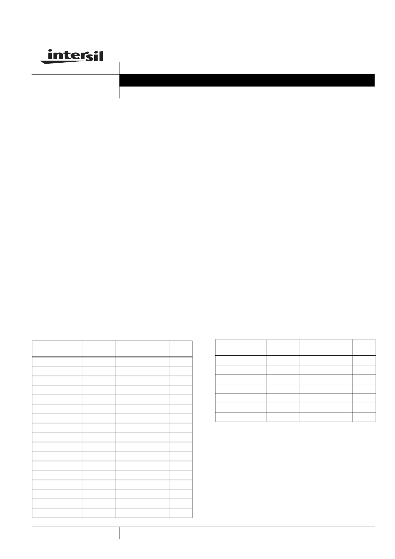
Ordering Information
PART NUMBER
TEMP.
RANGE (°C)
PACKAGE
PKG.
DWG. #
HI1-0506-2
-55 to 125
28 Ld CERDIP
F28.6
HI1-0506-5
0 to 75
28 Ld CERDIP
F28.6
HI4P0506-5
0 to 75
28 Ld PLCC
N28.45
HI4P0506-5Z (Note)
0 to 75
28 Ld PLCC (Pb-free) N28.45
HI9P0506-9
-40 to 85
28 Ld SOIC
M28.3
HI9P0506-9Z (Note)
-40 to 85
28 Ld SOIC (Pb-free) M28.3
HI1-0507-2
-55 to 125
28 Ld CERDIP
F28.6
HI3-0507-5
0 to 75
28 Ld PDIP
E28.6
HI1-0508-2
-55 to 125
16 Ld CERDIP
F16.3
HI1-0508-5
0 to 75
16 Ld CERDIP
F16.3
HI3-0508-5
0 to 75
16 Ld PDIP
E16.3
HI3-0508-5Z (Note)
0 to 75
16 Ld PDIP (Pb-free) E16.3
HI9P0508-5
0 to 75
16 Ld SOIC
M16.15
HI9P0508-5Z (Note)
0 to 75
16 Ld SOIC (Pb-free) M16.15
HI9P0508-9
-40 to 85
16 Ld SOIC
M16.15
HI9P0508-9Z (Note)
-40 to 85
16 Ld SOIC (Pb-free) M16.15
HI1-0509-2
-55 to 125
16 Ld CERDIP
F16.3
HI1-0509-4
-25 to 85
16 Ld CERDIP
F16.3
HI1-0509-5
0 to 75
16 Ld CERDIP
F16.3
HI3-0509-5
0 to 75
16 Ld PDIP
E16.3
HI4P0509-5
0 to 75
20 Ld PLCC
N20.35
HI4P0509-5Z (Note)
0 to 75
20 Ld PLCC (Pb-free) N20.35
HI9P0509-5
0 to 75
16 Ld SOIC
M16.15
HI9P0509-5Z (Note)
0 to 75
16 Ld SOIC (Pb-free) M16.15
NOTE: Intersil Pb-free plus anneal products employ special Pb-free
material sets; molding compounds/die attach materials and 100%
matte tin plate termination finish, which are RoHS compliant and
compatible with both SnPb and Pb-free soldering operations. Intersil
Pb-free products are MSL classified at Pb-free peak reflow
temperatures that meet or exceed the Pb-free requirements of
IPC/JEDEC J STD-020.
Ordering Information
PART NUMBER
TEMP.
RANGE (°C)
PACKAGE
PKG.
DWG. #
相關PDF資料 |
PDF描述 |
|---|---|
| HI3-0516-5Z | 16-Channel/Differential 8-Channel, CMOS High Speed Analog Multiplexer |
| HI3-0516-5 | 16-Channel/Differential 8-Channel, CMOS High Speed Analog Multiplexer |
| HI-516 | 69 MACROCELL 3.3 VOLT ISP CPLD - NOT RECOMMENDED for NEW DESIGN |
| HI3-0518-5Z | 8-Channel/Differential 4-Channel, CMOS High Speed Analog Multiplexer |
| HI3-0518-5 | RESISTOR POWER 125 OHM 8W 5% |
相關代理商/技術參數(shù) |
參數(shù)描述 |
|---|---|
| HI4P0509-5Z96 | 功能描述:多路器開關 IC MUX DIFF 4:1 20PLCC COM RoHS:否 制造商:Texas Instruments 通道數(shù)量:1 開關數(shù)量:4 開啟電阻(最大值):7 Ohms 開啟時間(最大值): 關閉時間(最大值): 傳播延遲時間:0.25 ns 工作電源電壓:2.3 V to 3.6 V 工作電源電流: 最大工作溫度:+ 85 C 安裝風格:SMD/SMT 封裝 / 箱體:UQFN-16 |
| HI4P0516-5 | 制造商:Rochester Electronics LLC 功能描述:- Bulk 制造商:Harris Corporation 功能描述: |
| HI4P0518-5 | 制造商:Rochester Electronics LLC 功能描述:- Bulk |
| HI4P0524-5 | 制造商:Rochester Electronics LLC 功能描述:- Bulk |
| HI4P0539 | 制造商:未知廠家 制造商全稱:未知廠家 功能描述:Interface IC |
發(fā)布緊急采購,3分鐘左右您將得到回復。