- 您現(xiàn)在的位置:買賣IC網(wǎng) > PDF目錄384398 > HE83R123 (King Billion Electronics Co., Ltd.) oscillator clocks. This chip is suitable for the applications that require higher performance PDF資料下載
參數(shù)資料
| 型號(hào): | HE83R123 |
| 廠商: | King Billion Electronics Co., Ltd. |
| 英文描述: | oscillator clocks. This chip is suitable for the applications that require higher performance |
| 中文描述: | 振蕩器時(shí)鐘。該芯片適用于適用于需要更高的性能 |
| 文件頁數(shù): | 7/18頁 |
| 文件大小: | 335K |
| 代理商: | HE83R123 |
King Billion Electronics Co., Ltd
駿
億
電
子
股
份
有
限
公
司
HE83R123
HE80000 Series
LVF pads.
March 13, 2003
This specification is subject to change without notice. Please contact sales person for the latest version before use.
7
V1.0E
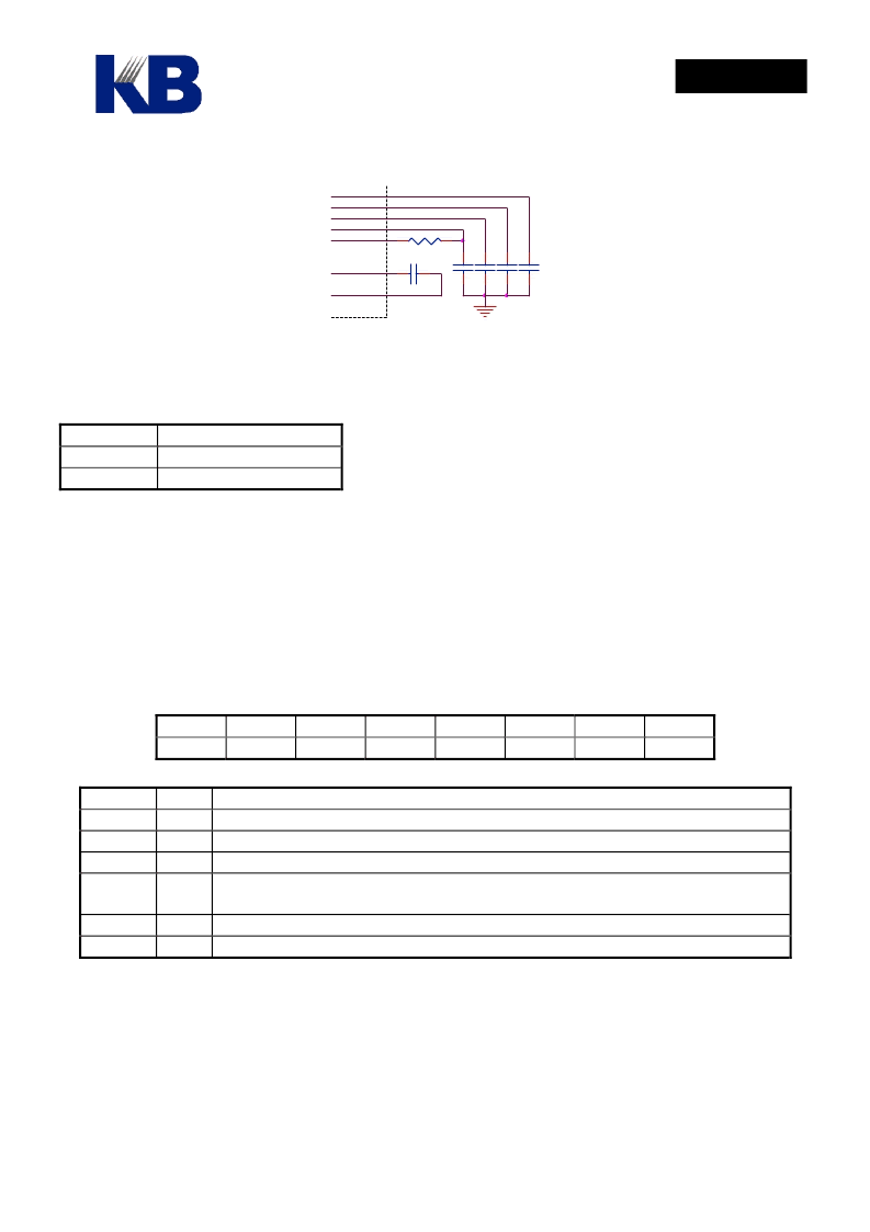
LV4
LV3
LV2
LV1
LVF
LC2
LC1
104
0.1uF
R
0.1uF
0.1uF
0.1uF
With the regulated LCD power, the LCD display can give steady visual effect over a wide range of
operating voltage. The built-in regulator must be enabled by mask option MO_ LVRG to function.
MO_LVRG Function
0
1
Disable LCD regulator
Enable LCD regulator
Please note that to emulate the visual effect of 1/4 bias on the ICE 3.X version the LR2 and LR3 on the
top board need be shorted.
6.
LCDC Control register
LCD Control Register LCDC controls the functions of LCD driver; such as contrast level, LCD
waveform type, On/Off, Blank, etc.
LCDC
bit 7
-
bit 6
-
bit 5
-
bit 4
-
bit 3
-
bit 2
TYPE
bit 1
BLANK LCDE
bit 0
Field
TYPE
BLANK
Value Function
0
Select Type A LCD waveform
1
Select Type B LCD waveform
0
Normal display
1
LCD display blanked. LCD driver changes only COM output signal, SEG
signal remains unchanged.
0
LCD driver disabled, LCD driver has no output signal.
1
LCD driver Enabled
LCDE
Please note that LCD driver must be turned off before the entering sleep mode. That means user must
clear the bit 0 of LCDC to turn off LCD driving circuit before setting bit 6 of OP1 to enter sleep mode.
Large current might happen if the procedure is not followed.
Please also note that LCD driver uses slow clock as clock source. The LCD display will not display
normally if it works in Fast clock only mode because the LCD refresh action is too fast.
相關(guān)PDF資料 |
PDF描述 |
|---|---|
| HE83R125 | This chip is suitable for the applications that require higher performance |
| HE83R126 | 8-BIT MICRO-CONTROLLER |
| HE83R141 | 8-BIT MICRO-CONTROLLER |
| HE83R142 | 8-BIT MICRO-CONTROLLER |
| HE83R143 | 8-BIT MICRO-CONTROLLER |
相關(guān)代理商/技術(shù)參數(shù) |
參數(shù)描述 |
|---|---|
| HE83R123(S) | 制造商:未知廠家 制造商全稱:未知廠家 功能描述: |
| HE83R125 | 制造商:KB 制造商全稱:KB 功能描述:This chip is suitable for the applications that require higher performance |
| HE83R125(S) | 制造商:未知廠家 制造商全稱:未知廠家 功能描述: |
| HE83R126 | 制造商:KB 制造商全稱:KB 功能描述:8-BIT MICRO-CONTROLLER |
| HE83R141 | 制造商:KB 制造商全稱:KB 功能描述:8-BIT MICRO-CONTROLLER |
發(fā)布緊急采購,3分鐘左右您將得到回復(fù)。