- 您現(xiàn)在的位置:買賣IC網(wǎng) > PDF目錄370460 > HD404668 (Hitachi,Ltd.) Low-Voltage AS Microcomputers with On-Chip DTMF Generation Circuit(帶雙音多頻電路的低電壓微計(jì)算機(jī)) PDF資料下載
參數(shù)資料
| 型號: | HD404668 |
| 廠商: | Hitachi,Ltd. |
| 英文描述: | Low-Voltage AS Microcomputers with On-Chip DTMF Generation Circuit(帶雙音多頻電路的低電壓微計(jì)算機(jī)) |
| 中文描述: | 低電壓如同在微機(jī)芯片的DTMF產(chǎn)生電路(帶雙音多頻電路的低電壓微計(jì)算機(jī)) |
| 文件頁數(shù): | 81/142頁 |
| 文件大小: | 894K |
| 代理商: | HD404668 |
第1頁第2頁第3頁第4頁第5頁第6頁第7頁第8頁第9頁第10頁第11頁第12頁第13頁第14頁第15頁第16頁第17頁第18頁第19頁第20頁第21頁第22頁第23頁第24頁第25頁第26頁第27頁第28頁第29頁第30頁第31頁第32頁第33頁第34頁第35頁第36頁第37頁第38頁第39頁第40頁第41頁第42頁第43頁第44頁第45頁第46頁第47頁第48頁第49頁第50頁第51頁第52頁第53頁第54頁第55頁第56頁第57頁第58頁第59頁第60頁第61頁第62頁第63頁第64頁第65頁第66頁第67頁第68頁第69頁第70頁第71頁第72頁第73頁第74頁第75頁第76頁第77頁第78頁第79頁第80頁當(dāng)前第81頁第82頁第83頁第84頁第85頁第86頁第87頁第88頁第89頁第90頁第91頁第92頁第93頁第94頁第95頁第96頁第97頁第98頁第99頁第100頁第101頁第102頁第103頁第104頁第105頁第106頁第107頁第108頁第109頁第110頁第111頁第112頁第113頁第114頁第115頁第116頁第117頁第118頁第119頁第120頁第121頁第122頁第123頁第124頁第125頁第126頁第127頁第128頁第129頁第130頁第131頁第132頁第133頁第134頁第135頁第136頁第137頁第138頁第139頁第140頁第141頁第142頁
HD404669 Series
81
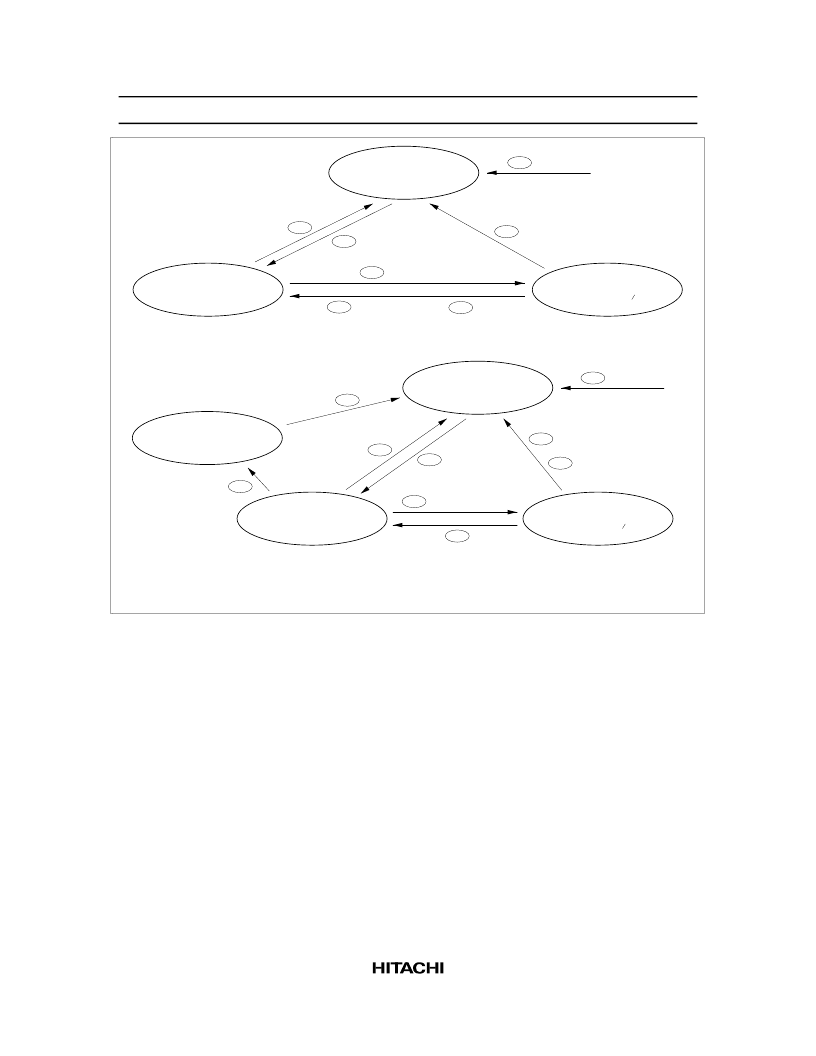
STS wait state
(Octal counter 1 = 000,
transmit clock disabled)
Transmit clock wait state
(Octal counter 1 = 000)
Trans
fer
state
(Octal counter 1 = 000)
MCU reset
00
SM1A write
04
STS instruction
01
Transmit clock
02
8 transmit clocks
03
STS instruction (IFS1 1)
05
SM1A write (IFS1 1)
06
External clock mode
STS wait state
(Octal counter 1 = 000,
transmit clock disabled)
Transmit clock wait state
(Octal counter 1 = 000)
Transfer state
(Octal counter 1 = 000)
SM1A write
14
STS instruction
11
Transmit clock
12
15
STS instruction (IFS1 1)
8 transmit clocks
13
Internal clock mode
Continuous clock output state
(PMRA 0, 1 = 00)
SM1A write
18
Transmit clock
17
16
Note: Refer to the Operating States section for the corresponding encircled numbers.
MCU reset
10
SM1A write (IFS1 1)
Figure 59 Serial Interface State Transitions
Transmit clock wait state: Transmit clock wait state is between the STS execution and the falling edge
of the first transmit clock. In transmit clock wait state, input of the transmit clock (02, 12) increments
the octal counter, shifts the serial data register 1 (SR1L: $006, SR1U: $007), and enters the serial
interface in transfer state. However, note that if continuous clock output mode is selected in internal
clock mode, the serial interface does not enter transfer state but enters continuous clock output state
(17).
The serial interface enters STS wait state by writing data to serial mode register 1A (SM1A: $005) (04,
14) in transmit clock wait state.
Transfer state: Transfer state is between the falling edge of the first clock and the rising edge of the
eighth clock. In transfer state, the input of eight clocks or the execution of the STS instruction sets the
octal counter to 000, and the serial interface enters another state. When the STS instruction is executed
(05, 15), transmit clock wait state is entered. When eight clocks are input, transmit clock wait state is
entered (03) in external clock mode, and STS wait state is entered (13) in internal clock mode. In
internal clock mode, the transmit clock stops after outputting eight clocks.
In transfer state, writing data to serial mode register 1A (SM1A: $005) (06, 16) initializes the serial
interface, and STS wait state is entered.
相關(guān)PDF資料 |
PDF描述 |
|---|---|
| HD404669 | Low-Voltage AS Microcomputers with On-Chip DTMF Generation Circuit(帶雙音多頻電路的低電壓微計(jì)算機(jī)) |
| HD407A4669 | Low-Voltage AS Microcomputers with On-Chip DTMF Generation Circuit(帶雙音多頻電路的低電壓微計(jì)算機(jī)) |
| HD404719FS | Five timer/counters |
| HD404439FS | Five timer/counters |
| HD4074719FS | Five timer/counters |
相關(guān)代理商/技術(shù)參數(shù) |
參數(shù)描述 |
|---|---|
| HD404668H | 制造商:HITACHI 制造商全稱:Hitachi Semiconductor 功能描述:Low-Voltage AS Microcomputers with On-Chip DTMF Generation Circuit |
| HD404669 | 制造商:HITACHI 制造商全稱:Hitachi Semiconductor 功能描述:Low-Voltage AS Microcomputers with On-Chip DTMF Generation Circuit |
| HD404669H | 制造商:HITACHI 制造商全稱:Hitachi Semiconductor 功能描述:Low-Voltage AS Microcomputers with On-Chip DTMF Generation Circuit |
| HD404669SERIES | 制造商:未知廠家 制造商全稱:未知廠家 功能描述: |
| HD404676H | 制造商:未知廠家 制造商全稱:未知廠家 功能描述:4-Bit Microcontroller |
發(fā)布緊急采購,3分鐘左右您將得到回復(fù)。